Method and apparatus for verifying temperature during integrated circuit thermal testing

a technology for thermal testing and integrated circuits, which is applied in the direction of electrical testing, measurement devices, instruments, etc., can solve the problems of duts falling out of the specified temperature range, other (typically less expensive) ic devices not including this temperature diode, and actual temperature of duts deviating significantly from the temperature, so as to achieve accurate estimation of actual test temperatur

Active Publication Date: 2005-10-18
XILINX INC
View PDF16 Cites 17 Cited by
  • Summary
  • Abstract
  • Description
  • Claims
  • Application Information

AI Technical Summary

Benefits of technology

[0012]The present invention is directed to a method for verifying the temperature of a QFP-type IC device during thermal testing that overcomes the problems associated with conventional thermal testing methods by utilizing a special test block that...

Problems solved by technology

However, other (typically less-expensive) IC devices do not include this temperature diode, and require the use of other temperature verification procedures.
A problem with the conventional verification procedure described above is that several factors can cause the actual temperature of the DUTs to deviate significantly from the temperature measured by the heater block and/or from the specified test temperature.
For example, any increased resistance in the cable connected to the heat sensor of the heater block (e.g., due to motion, age, or oxidation) can cause the ATE system to erroneously determine that the DUT is hotter than it really is, and the heater block will compensate by turning off the heater unit/and or driving do...

Method used


Image

  • Method and apparatus for verifying temperature during integrated circuit thermal testing
  • Method and apparatus for verifying temperature during integrated circuit thermal testing
  • Method and apparatus for verifying temperature during integrated circuit thermal testing

Examples


Embodiment Construction

[0022]An exemplary embodiment of the present invention is described below as being utilized to verify the thermal testing temperature of QFP-type IC that do not include on-chip temperature measuring diodes. Those of ordinary skill in the art will recognize that the methods and structures associated with the present invention may be extended to IC package types other than QFP-type devices, and may be utilized to verify temperatures read from ICs having on-chip temperature measuring diodes. Therefore, the present invention is limited only by the appended claims.

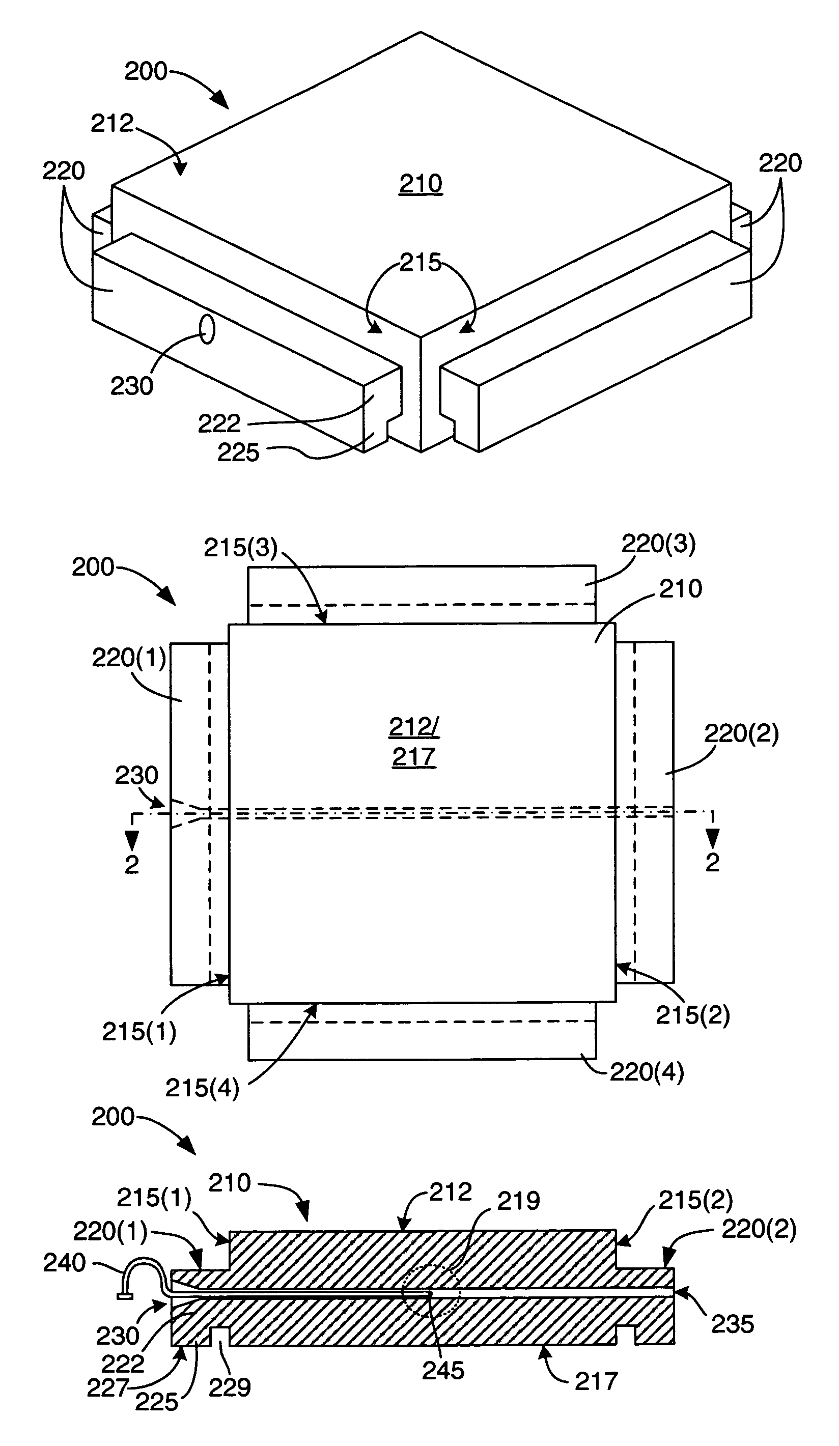
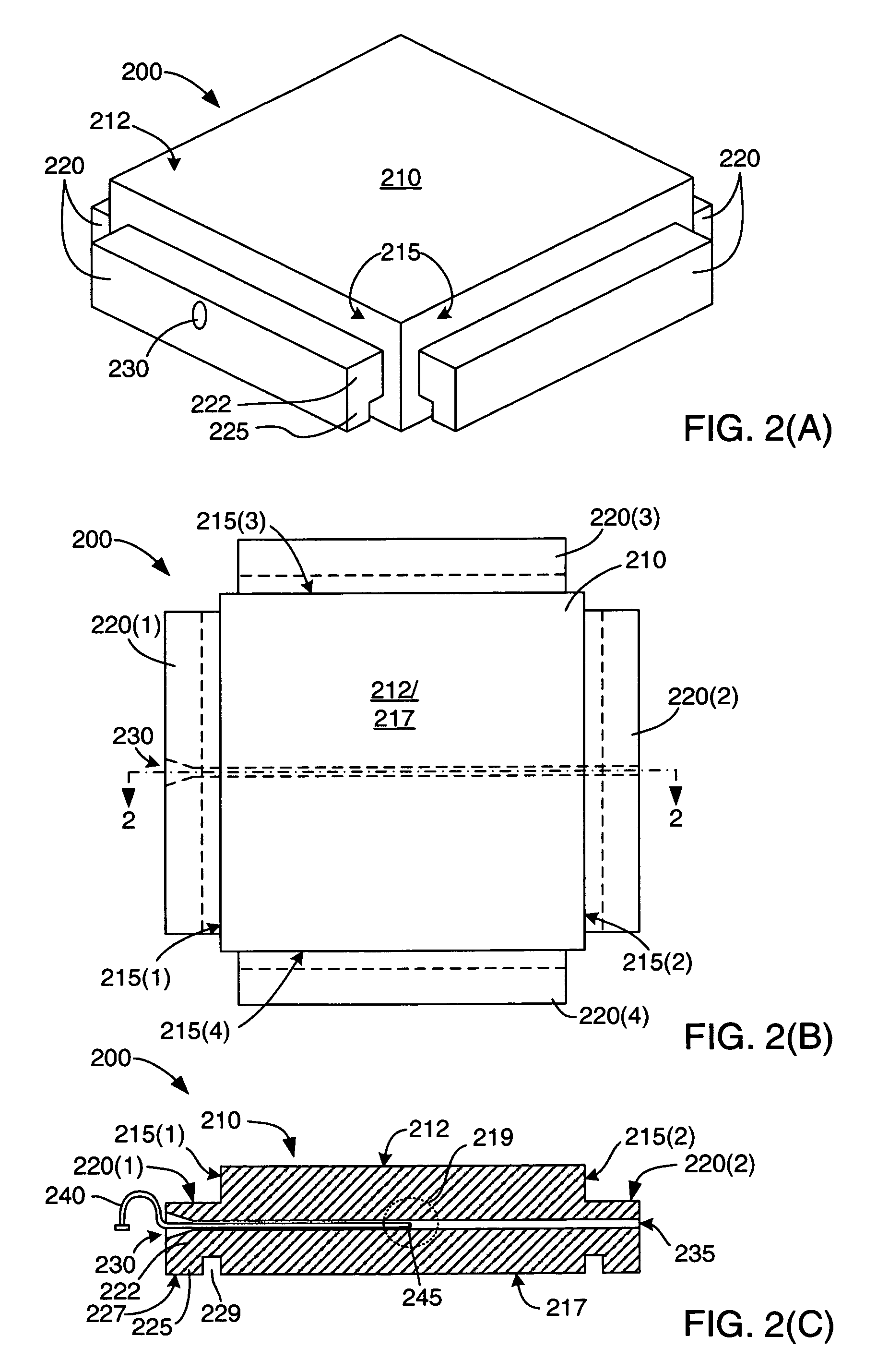
[0023]FIGS. 2(A), 2(B), and 2(C) show an exemplary test block 200 that is utilized in the manner described below to verity the temperature of a QFP-type IC device during thermal testing. As described in additional detail below, test block 200 is utilized to measure the temperature between a test head and a test socket in an ATE system. This temperature is then used to verify that QFP-type IC devices subsequently (or previously)...


PUM


Abstract

An test block includes a box-like body and four rails extending from side edges of the body. During thermal testing, the test block is mounted between a test head and a test socket such that the rails provide a thermal path between the test block body and contact pads formed on the test socket. In this manner the rails emulate the thermal path formed by the metal leads extending from a conventional Quad Flat Pack Integrated Circuit (QFP IC), thereby reliably duplicating the actual thermal path of the QFP IC. The test block is mounted on the test system and its temperature is measured before and after testing QFP IC devices. Confirming that the test block is within test temperature specifications before and after the QFP-IC test procedure provides a highly reliable verification that the QFP-IC's actual test temperature is within the test temperature specifications.

Description

FIELD OF THE INVENTION[0001]The present invention relates to automated test equipment for testing integrated circuits (ICs), and more particularly to apparatus and methods for verifying the temperature of Quad Flat Pack-type (QFP-type) IC devices during thermal testing.RELATED ART[0002]Packaged integrated circuits (ICs) are often tested at a selected high or low temperature (e.g., 100° C.) to verify that the ICs function properly at the selected temperature. This thermal testing process is typically carried out using automatic test equipment (ATE) system that includes an IC test signal generator (IC tester), a test fixture (e.g., a socket) for transmitting electrical signals from the IC test signal generator to an IC device-under-test (DUT), and a handler system that is positioned inside of an insulated chamber and moves the DUTs between a shipping tray and the test fixture. Thermal testing typically involves verifying that the IC DUTs were tested at least at the specified temperatu...

Claims


Application Information

Patent Timeline
IPC IPC(8): G01R31/02G01R31/26G01R1/04
CPCG01R1/0458
Inventor FELTNER, THOMAS A.AYLETT, JAMES S.MARLEY, JOHN C.GALLAGHER, THOMAS A.
Owner XILINX INC
Why Eureka
Try Eureka