
System and method for measuring object characteristics using phase differences in polarized light reflections

a technology of polarized light reflection and phase difference, applied in the field of thin film measurement, can solve the problems of inability to measure in situ wear, lubricant and surface roughness, and inability to maximize the operating life of the hard disk,

Inactive Publication Date: 2005-10-18
KLA TENCOR TECH CORP
View PDF69 Cites 40 Cited by
  • Summary
  • Abstract
  • Description
  • Claims
  • Application Information

AI Technical Summary

Benefits of technology

"The invention is a system and method for measuring properties of thin film disks using an optical system that transmits electromagnetic radiation towards the disk at an angle of incidence that need not be substantially Brewster's angle. The system can measure lubricant thickness and degradation, carbon wear and thickness, and surface roughness of thin film magnetic disks. The focused optical light incident at an angle to the surface of the disk allows for easy measurement of changes in lubricant thickness, carbon thickness, and surface roughness."

Problems solved by technology

One problem that the manufacturers of hard disks experience is how to maximize the operating life of a hard disk.
When a hard disk fails the data stored therein may be difficult, expensive, or impossible to retrieve.
These references relate to obtaining the surface roughness and do not address identifying lubricant thickness and degradation or thin film thickness or wear.
The system as described is designed for ex situ measurement of film thickness and surface microroughness, it is not capable of measuring in situ wear, lubricant and surface roughness.
None of these references teach a single system and method for performing all of these measurements in situ.

Method used


Image

  • System and method for measuring object characteristics using phase differences in polarized light reflections
  • System and method for measuring object characteristics using phase differences in polarized light reflections
  • System and method for measuring object characteristics using phase differences in polarized light reflections

Examples


Embodiment Construction

[0049]A preferred embodiment of the present invention is now described with reference to the figures where like reference numbers indicate identical or functionally similar elements. Also in the figures, the left most digit(s) of each reference number correspond(s) to the figure in which the reference number is first used.

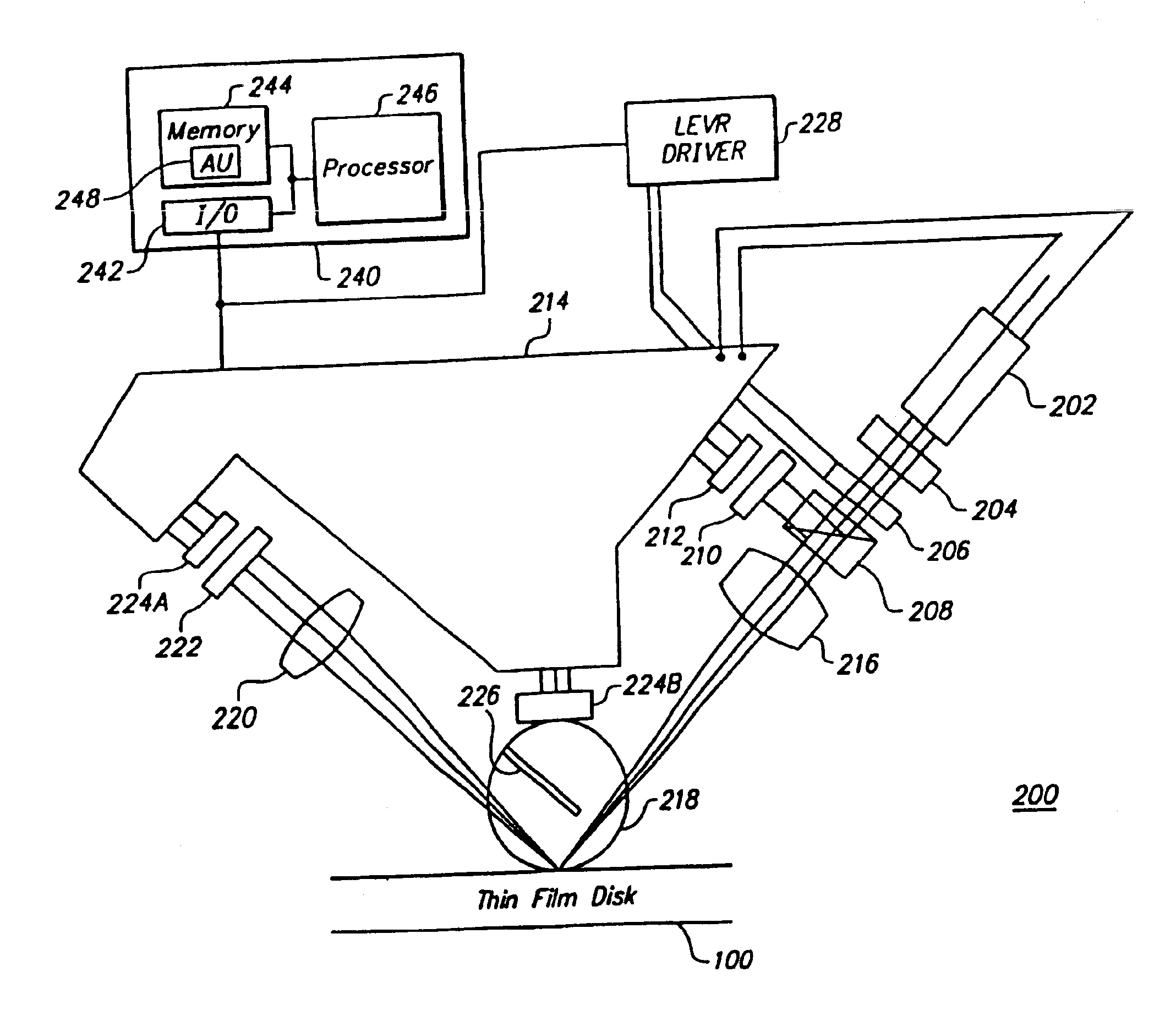
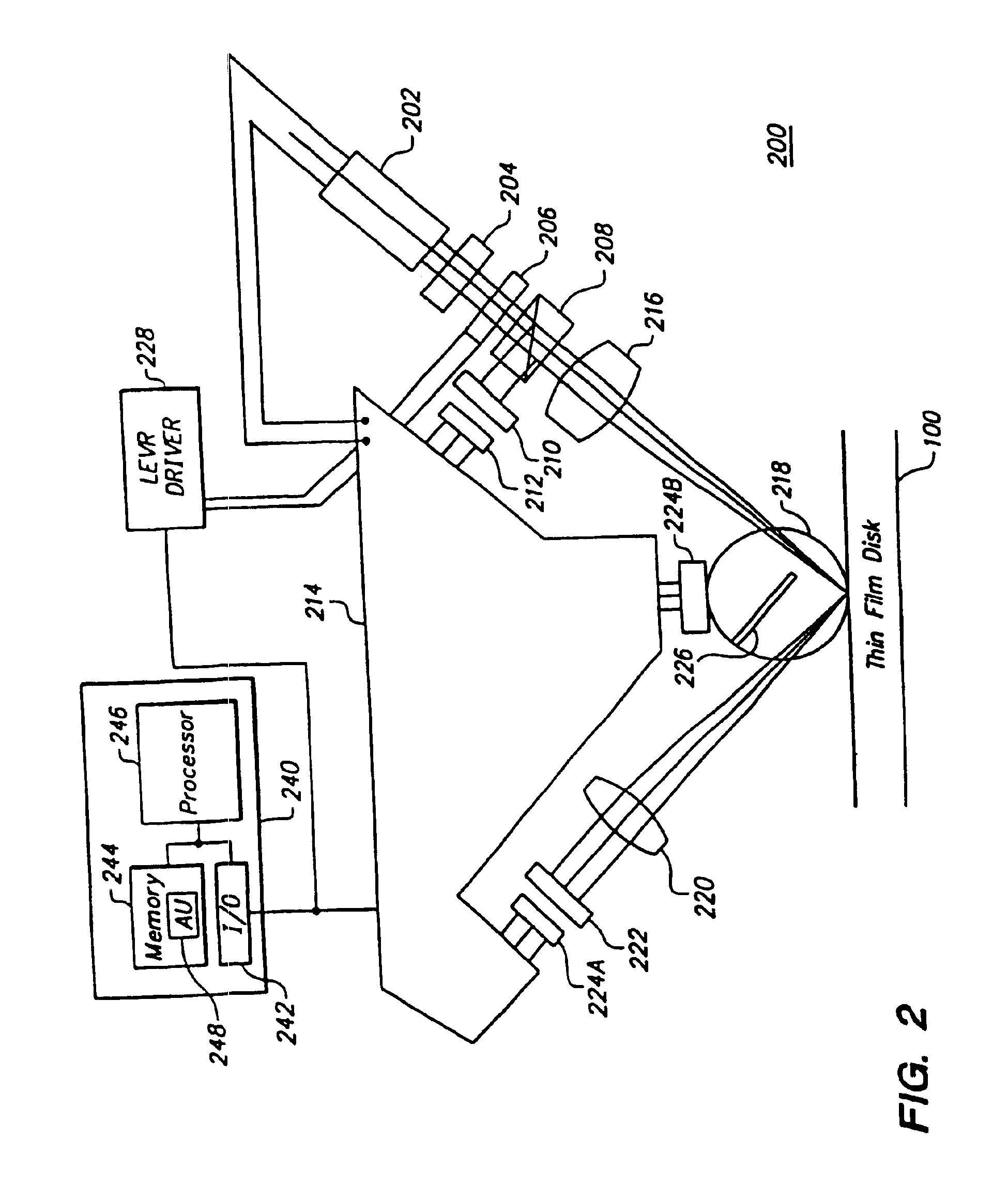
[0050]FIG. 2 is an illustration of an apparatus for measuring properties of the thin film according to the preferred embodiment of the present invention. The apparatus uses a focused laser light signal whose angle of propagation can be between zero degrees from normal and ninety degrees from normal.

[0051]One embodiment of the apparatus 200 includes a conventional laser diode 202, e.g., SLD 104AU available from Sony, Tokyo, Japan, which has been collimated by Hoetron Corp., Sunnyvale, Calif., e.g., a conventional linear polarizer 204, e.g., made of Polarcor that is commercially available from Newport Corp., Irvine, Calif., a conventional liquid crystal variable reta...


PUM

PropertyMeasurementUnit
thicknessaaaaaaaaaa
angleaaaaaaaaaa
angleaaaaaaaaaa

Abstract

A system and method for performing a magnetic imaging, optical profiling, and measuring lubricant thickness and degradation, carbon wear, carbon thickness, and surface roughness of thin film magnetic disks and silicon wafers at angles that are not substantially Brewster's angle of the thin film (carbon) protective overcoat is provided. The system and method involve a focused optical light whose polarization can be switched between P or S polarization is incident at an angle to the surface of the thin film magnetic disk. This generates both reflected and scattered light that may be measured to determine various values and properties related to the surface of the disk, including identifying the Kerr-effect in reflected light for determination of point magnetic properties. In addition, the present invention can mark the position of an identified defect.

Description

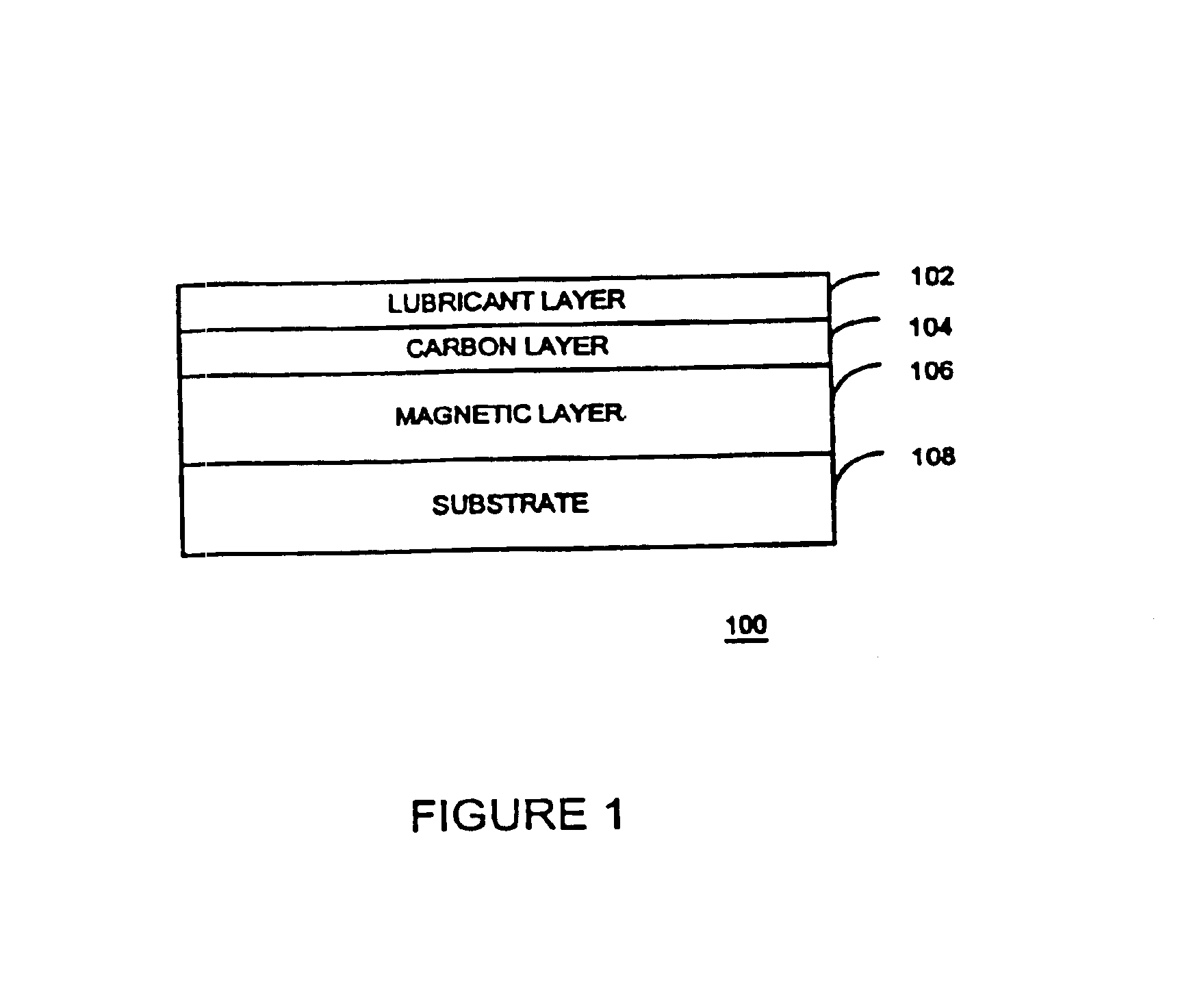
RELATED APPLICATIONS[0001]This application is a continuation of U.S. patent application Ser. No. 09 / 414,388 filed on 07 Oct. 1999 now U.S. Pat. No. 6,665,078, which is a continuation-in-part of U.S. patent application Ser. No. 09 / 347,622 filed on 02 Jul. 1999 now U.S. Pat. No. 6,717,671 which is a continuation-in-part of U.S. patent application Ser. No. 09 / 136,897 filed on 19 Aug. 1998, now U.S. Pat. No. 6,031,615, which claims priority from provisional application No. 60 / 059,740 filed on 22 Sept. 1997 which are all incorporated by reference herein in their entirety.BACKGROUND OF INVENTION[0002]1. Field of the Invention[0003]The present invention is directed toward measuring thin films including silicon wafers and more particularly toward measuring lubricant thickness, lubricant degradation, thin film thickness and wear, and surface roughness using a laser directed toward a thin film disk at many angles including non-Brewster's angles of an absorbing layer of the thin film.[0004]2. ...

Claims


Application Information

Patent Timeline
Patent Type & Authority Patents(United States)
IPC IPC(8): G01B11/06G01B11/30G01N21/21G01N21/47G01N21/95G11B5/84
CPCG01B11/065G01B11/303G01N21/211
Inventor MEEKS, STEVEN W.KUDINAR, RUSMIN
Owner KLA TENCOR TECH CORP
Learn More