
Arrayed waveguide gratings with improved transmission efficiency

a waveguide and grating technology, applied in the field of arrayed waveguide gratings, can solve the problems of limited spectral width, limited maximum channel count or maximum spectral width of this kind of device, and limitations, so as to maximize the weakest wavelength signal transmission coefficient and increase the transmission coefficient of awg.

Inactive Publication Date: 2005-10-18
LUCENT TECH INC
View PDF18 Cites 7 Cited by
  • Summary
  • Abstract
  • Description
  • Claims
  • Application Information

AI Technical Summary

Benefits of technology

[0007]The present invention advantageously provides for an arrayed waveguide grating with improved transmission efficiency.
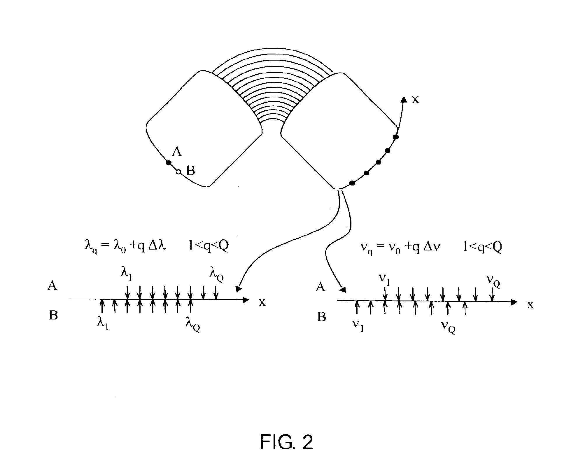
[0008]In one embodiment of the present invention a method for improving the transmission efficiency of an arrayed waveguide grating (AWG) comprising P input ports and Q output ports (P×Q AWG), includes a novel positioning of the ports at the input of a first P×M star coupler and at the output of a second M×Q star coupler, M being the number of waveguides connecting the star couplers. The novel method used to determine the optimum position of the ports ensures that the maximum frequency deviation between the signal frequency and the center of the corresponding transmission passband is minimal for all possible connections among input and output ports.

Problems solved by technology

The use of AWGs, however, presents some limitations.
Due to the intrinsic diffraction characteristics of an AWG, the maximum channel count or maximum spectral width of this kind of devices may be limited.
Additional limitations arise if the AWG is designed to cross-connect channels that are equally spaced in frequency to be compliant with the industry International Telecommunications Union (ITU) standard frequency grid as opposed to being equally spaced in wavelength (see e.g. P. Bernasconi, C. Doerr, C. Dragone, M. Cappuzzo, E. Laskpwski, and A. Paunescu, “Large N×N Waveguide grating routers,”J.

Method used


Image

  • Arrayed waveguide gratings with improved transmission efficiency
  • Arrayed waveguide gratings with improved transmission efficiency
  • Arrayed waveguide gratings with improved transmission efficiency

Examples


Embodiment Construction

[0019]The present invention advantageously provides for an arrayed waveguide grating with improved transmission efficiency. Although embodiments of the present invention are being described herein with respect to P×Q arrayed waveguide gratings (AWGs), it will be appreciated by those skilled in the art informed by the teachings of the present invention, that the concepts of the present invention may be applied to AWGs of various other input and output port configurations and even further to other optical cross connect switches and devices.

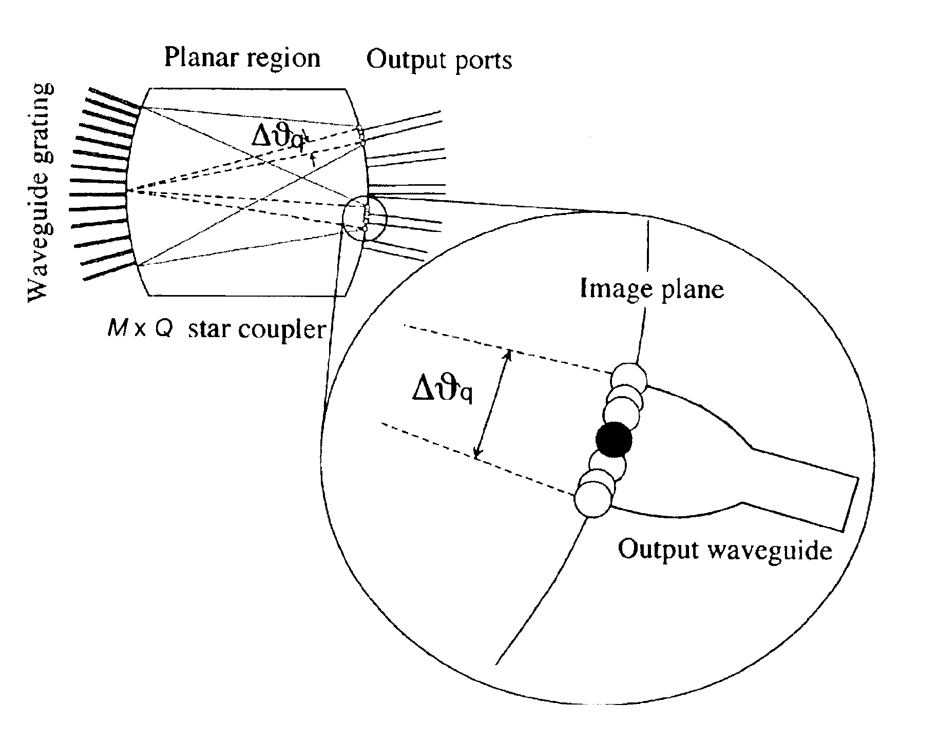
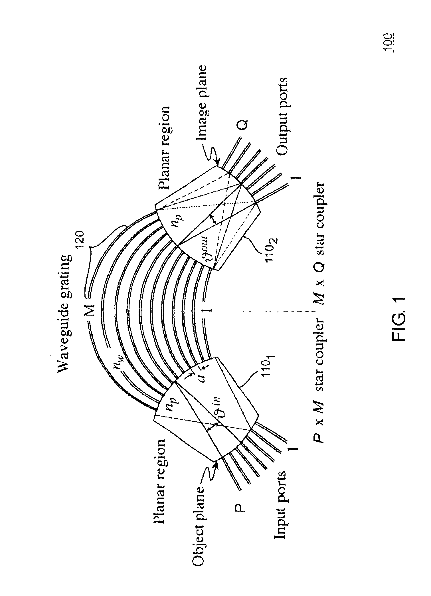
[0020]FIG. 1 depicts a high-level block diagram of an embodiment of an arrayed waveguide grating (AWG). The AWG 100 of FIG. 1 is essentially an imaging system where the object and the image planes lie at opposite sides of two star couplers 1101, 1102 connected by M waveguides 120 of unequal lengths. The desired diffraction properties arise from the varying lengths (typically linearly increasing lengths) of the M waveguides 120, such that different w...


PUM


Abstract

An arrayed waveguide grating (AWG) with improved transmission efficiency includes an input P×M star coupler, an output M×Q star coupler, and M waveguides of unequal length connecting the input and output star couplers. A novel method used to determine the optimum position of the ports ensures that the maximum frequency deviation between the signal frequency and the center of the corresponding transmission passband is minimal for all possible connections among input and output ports.

Description

CROSS-REFERENCE TO RELATED APPLICATIONS[0001]This application is related to U.S. Pat. No. 6,381,383, issued Apr. 30, 2002, which is incorporated herein by reference in its entirety.FIELD OF THE INVENTION[0002]This invention relates to the field of arrayed waveguide grating devices and, more specifically, to arrayed waveguide gratings with improved filter accuracy.BACKGROUND OF THE INVENTION[0003]In order to meet the ever-increasing demand for transmission bandwidth in communication networks, the development of techniques for Wavelength Division Multiplexing (WDM) is increasing in importance. In particular, in dense WDM (DWDM), the use of the available optical bandwidth is optimized by increasing the system spectral efficiency (i.e., the ratio between signal bandwidth and channel spacing). This is achieved by employing many closely spaced carrier wavelengths multiplexed together onto a single waveguide such as an optical fiber and / or by increasing the signal modulation speed of every...

Claims


Application Information

Patent Timeline
Patent Type & Authority Patents(United States)
IPC IPC(8): G02B6/34
CPCG02B6/12016
Inventor BERNASCONI, PIETRO ARTURO GIOVANNI
Owner LUCENT TECH INC
Learn More