Self-calibrated ultrasonic method of in-situ measurement of borehole fluid acoustic properties

a technology of in-situ measurement and borehole fluid, which is applied in the field of determining the acoustic properties of borehole fluid, can solve the problems of loss of drilling fluid, invasion of the wellbore, and more difficult to measure the properties of virgin formation

Inactive Publication Date: 2005-10-25
HALLIBURTON ENERGY SERVICES INC
View PDF11 Cites 37 Cited by
  • Summary
  • Abstract
  • Description
  • Claims
  • Application Information

AI Technical Summary

Problems solved by technology

In overburdened wellbores, some of the drilling fluid penetrates into the formation, thereby causing a loss in the drilling fluid and forming an invaded zone around the wellbore.
It is desirable to reduce the fluid loss into the formation because it makes it more difficult to measure the properties of the virgin formation, which are required to determine the presence and retrievability of the trapped hydrocarbons.
In underbalanced drilling, the fluid column pressure is less than the formation pressure, which causes the formation fluid to enter into the wellbore.
This invasion may reduce the effectiveness of the drilling fluid.
Drilling of such boreholes requi

Method used


Image

  • Self-calibrated ultrasonic method of in-situ measurement of borehole fluid acoustic properties
  • Self-calibrated ultrasonic method of in-situ measurement of borehole fluid acoustic properties
  • Self-calibrated ultrasonic method of in-situ measurement of borehole fluid acoustic properties

Examples


Embodiment Construction

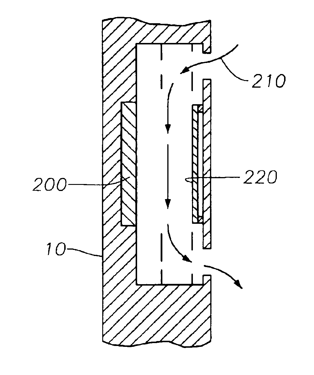
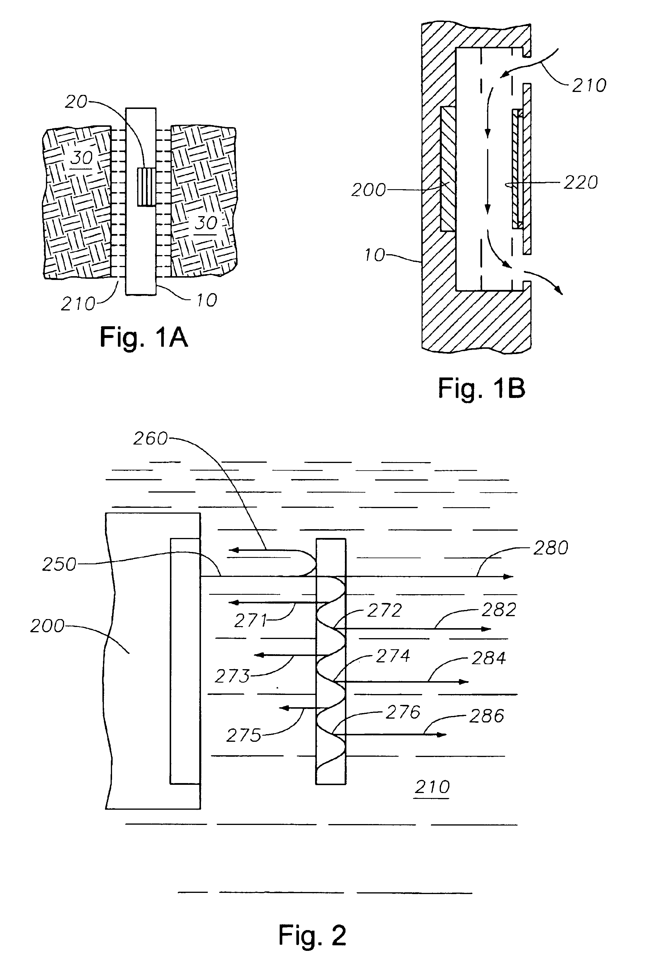
[0027]FIG. 1A illustrates a general overview of a tool submerged downhole. Shown are tool 10, fluid vent 20, formation 30, and well fluid 210. Fluid vent 20 provides a means for well fluid 210 to enter and exit tool 10. While in tool 10, well fluid 210 is measured for its acoustic properties.

[0028]FIG. 1B is a cross-sectional view of the tool showing acoustic measurement components. Inside tool 10, where fluid vent 20 is located, are acoustic transducer 200 and metal disk 220. As can be seen, well fluid 210 enters tool 10, flows between acoustic transducer 200 and metal disk 220, and exits tool 10.

[0029]FIG. 2 illustrates the acoustic wave path and metal disk reverberations for a downhole acoustic wave. Shown are acoustic transducer 200, well fluid 210 and metal disk 220. Well fluid 210 and disk 220 each has its own impedance, labeled Zm and Zs, respectively. Also shown is acoustic signal 250, including first reflected portion 260, disk reverberation portions 271-276 and transmitted...


PUM


Abstract

Tools and methods are provided that determine the acoustic impedance of drilling fluid using reflections from a precise metal disk. Because the reverberation characteristics of an acoustic wave depend in part on the acoustic wave shape, the first reflection from the metal disk may be used to calibrate the measurement. A method for determining a borehole fluid property includes (i) generating an acoustic signal within a borehole fluid, (ii) receiving reflections of the acoustic signal from the fluid, and (iii) analyzing a reverberation portion of the acoustic signal to determine the property. The analyzing of the reverberation portion may include obtaining a theoretical reverberation signal and relating the measured reverberation signal with the theoretical reverberation signal to determine the borehole fluid property.

Description

CROSS-REFERENCE TO RELATED APPLICATIONS[0001]This application is a divisional of U.S. patent application Ser. No. 09 / 927,067 which was filed Aug. 9, 2001 now U.S. Pat. No. 6,712,138.STATEMENT REGARDING FEDERALLY SPONSORED RESEARCH OR DEVELOPMENT[0002]Not Applicable.BACKGROUND OF THE INVENTION[0003]1. Field of the Invention[0004]The present invention relates generally to oil well logging and monitoring. More particularly, the present invention relates to determining the acoustic properties of a borehole fluid.[0005]2. Description of the Related Art[0006]To recover oil and gas from subsurface formations, wellbores or boreholes are drilled by rotating a drill bit attached at an end of a drill string. The drill string includes a drill pipe or a coiled tubing that has a drill bit at its downhole end and a bottom hole assembly (BHA) above the drill bit. The wellbore is drilled by rotating the drill bit by rotating the tubing and / or by a mud motor disposed in the BHA. A drilling or wellbor...

Claims


Application Information

Patent Timeline
IPC IPC(8): E21B49/00G01N29/02G01N29/036G01N29/30G01N29/22G01N29/44G01N29/46G01N29/024E21B47/12G01H5/00G01H15/00G01N29/09
CPCE21B49/003G01N29/024G01N29/30G01N29/4418G01N29/46G01N2291/02818G01N2291/045
Inventor MANDAL, BATAKRISHNA
Owner HALLIBURTON ENERGY SERVICES INC
Why Eureka
Try Eureka