System to control axial thrust loads for steam turbines

Inactive Publication Date: 2005-10-25
GENERAL ELECTRIC CO
View PDF5 Cites 42 Cited by
  • Summary
  • Abstract
  • Description
  • Claims
  • Application Information

AI Technical Summary

Benefits of technology

[0020]Briefly stated, the present invention is directed to the control of axial thrust loads in a steam turbine. This is accomplished by controlling a pressure differential across a balance piston in a high pressure section of the turbine in response to variations in net thrust. An apparatus of the invention controls net thrust in the turbine in response to changes in the operating condition of the turbine. The turbine includes a thrust bearing installed between the low and intermediate pressure sections of the turbine and the h

Problems solved by technology

However, all currently available methods only control thrust under “normal” operating conditions.
The methods set out above cannot now dynamically or actively adjust the steam turbine's net thrust, either under normal conditions or during fault operations.
Though such pressure equalizing features help minimize axial thrust variations during normal operations, none control net thrust for turbines operating under fault conditions.
A number of fault operating conditions have the potential of creating large thrust forces.
This can result in a very large thru

Method used


Image

  • System to control axial thrust loads for steam turbines
  • System to control axial thrust loads for steam turbines
  • System to control axial thrust loads for steam turbines

Examples


Embodiment Construction

[0030]The following detailed description illustrates the invention by way of example and not by way of limitation. The description clearly enables one skilled in the art to make and use the invention, describes several embodiments, adaptations, variations, alternatives, and uses of the invention, including what is presently believed to be the best mode of carrying out the invention.

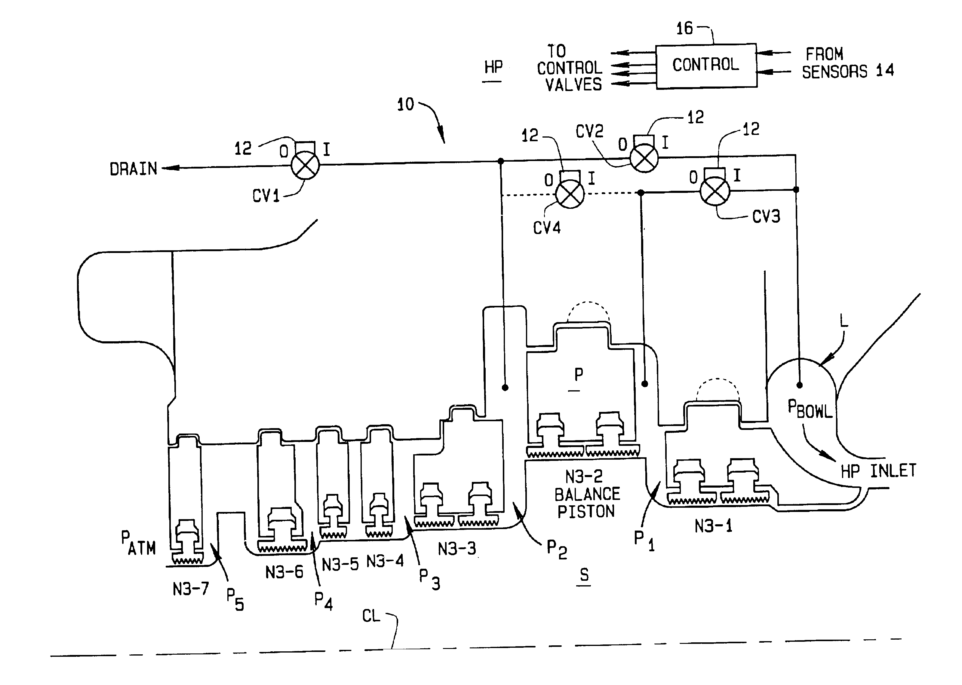
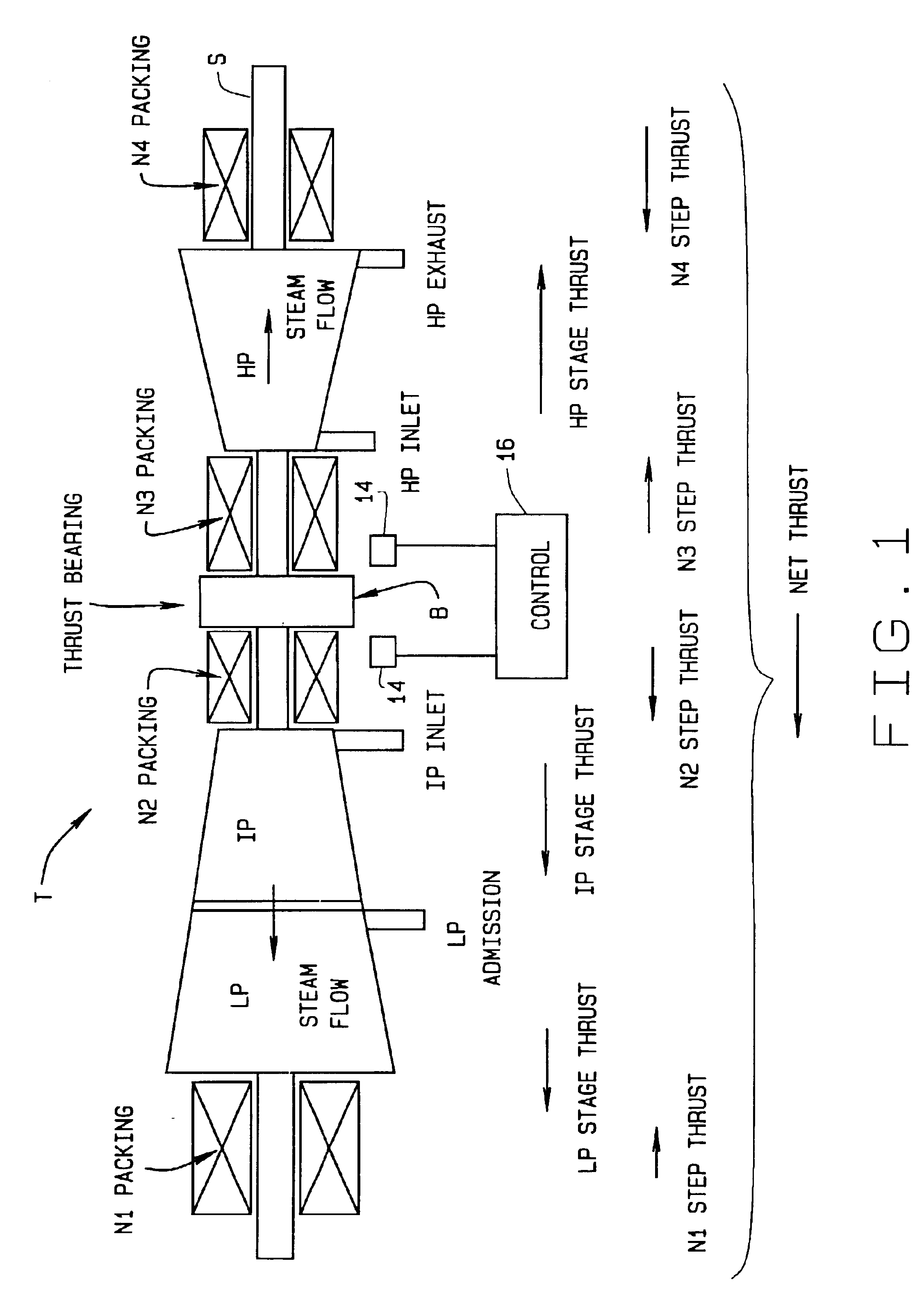
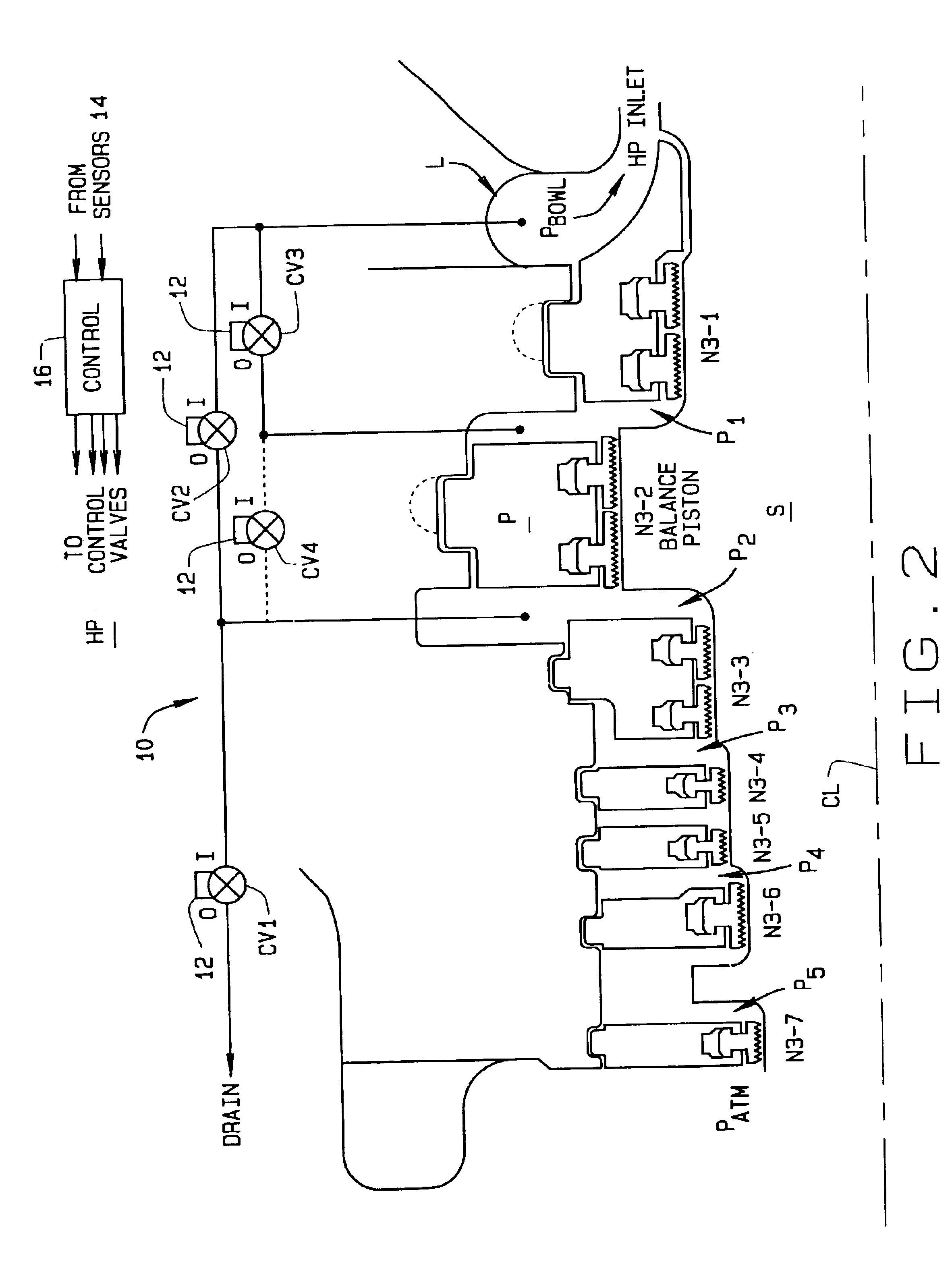
[0031]In accordance with the present invention, the net thrust load of a steam turbine is controlled by controlling the pressure differential across a balance piston in a high pressure section of the turbine in response to net thrust variation. Referring to FIG. 1, a turbine T is shown to be comprised of a high pressure section HP, an intermediate pressure section IP, and an adjacent low pressure section LP. Each section may be comprised of one or more stages. The rotating elements housed within these various stages are commonly mounted on an axial shaft or rotor S. As shown in FIG. 1, high pressure secti...


PUM


Abstract

Apparatus (10) controls net thrust in a steam turbine (T) in response to changes in the operating condition of the turbine. The turbine includes a thrust bearing (B) positioned between low and intermediate pressure sections (LP, IP) of the turbine and a high pressure section (HP) thereof. Sensors (14) for sense thrust loads on the thrust bearing. A number of control valve (CV1-CV4) are used to balance pressures occurring at locations within the high pressure section of the turbine. A controller (16) is responsive to the sensors sensing a change within the turbine indicative of a significant change in net thrust to energize one or more of the control valves and to adjust the pressure within the high pressure section of the turbine so to maintain net thrust within an acceptable range of thrust values.

Description

CROSS-REFERENCE TO RELATED APPLICATIONS[0001]None.STATEMENT REGARDING FEDERALLY SPONSORED RESEARCH OR DEVELOPMENT[0002]Not Applicable.BACKGROUND OF THE INVENTION[0003]This invention generally relates to steam turbines; and more specifically, to the development of a control system for stabilizing loading on thrust bearings within the turbine to maintain thrust levels within an acceptable range of values and avoid damage to the thrust bearings.[0004]In a rotating turbomachine, thrust is an axial force acting on the rotating parts. Thrust is caused by unequal pressures acting over unequal surface areas, and changes in momentum of the fluid (steam) circulating through the machine. The sum of all axial forces acting on the rotating components of the turbine is referred to as “net thrust”. This net thrust is transmitted to a stationary thrust bearing which, in turn, is anchored to a foundation for the turbine engine. The thrust developed by the turbine has two components. These are:[0005]...

Claims


Application Information

Patent Timeline
IPC IPC(8): F01D3/04F01D3/00
CPCF01D3/04
Inventor TONG, WEIVANDERVORT, CHRISTIAN L.
Owner GENERAL ELECTRIC CO
Why Eureka
Try Eureka