Acoustic driver assembly for a spherical cavitation chamber

a technology of acoustic driver and cavitation chamber, which is applied in the field ofsonoluminescence, can solve the problems of inadequate coupling lack of information about the coupling method of acoustic energy to the cavitation chamber, and many aspects of the phenomena that have not yet been characterized, and achieve the effect of maximum coupling efficiency

Inactive Publication Date: 2005-10-25
BURST ENERGIES INC
View PDF20 Cites 19 Cited by
  • Summary
  • Abstract
  • Description
  • Claims
  • Application Information

AI Technical Summary

Benefits of technology

[0015]The present invention provides an acoustic driver assembly for use with a spherical cavitation chamber. The acoustic driver assembly includes at least one transducer, a head mass and a tail mass, coupled together with a centrally located threaded means (e.g., all thread, bolt, etc.). The driver assembly is permanently attached to the exterior surface of the spherical cavitation chamber via diffusion bonding or brazing. In at least one embodiment, the transducer is comprised of a pair of piezo-electric transducers, preferably with the adjacent surfaces of the piezo-electric transducers having the same polarity. The surface of the head mass that is adjacent to the external surface of the chamber has a spherical curvature equivalent to the spherical curvature of the external surface of the chamber, thus providing maximum coupling efficiency between the acoustic driver and the cavitation chamber. In at least one embodiment a void filling material is interposed between one or more pairs of adjacent surfaces of the driver assembly. In at least one embodiment a two-piece head mass is used, thus allowing driver assembly / disassembly that is independent of the driver / chamber coupling.

Problems solved by technology

Although it is generally recognized that during the collapse of a cavitating bubble extremely high temperature plasmas are developed, leading to the observed sonoluminescence effect, many aspects of the phenomena have not yet been characterized.
Although acoustic drivers are commonly used to drive the cavitation process, there is little information about methods of coupling the acoustic energy to the cavitation chamber.
Although a variety of cavitation systems have been designed, these systems typically provide inadequate coupling of the acoustic energy to the cavitation chamber.

Method used


Image

  • Acoustic driver assembly for a spherical cavitation chamber
  • Acoustic driver assembly for a spherical cavitation chamber
  • Acoustic driver assembly for a spherical cavitation chamber

Examples


Embodiment Construction

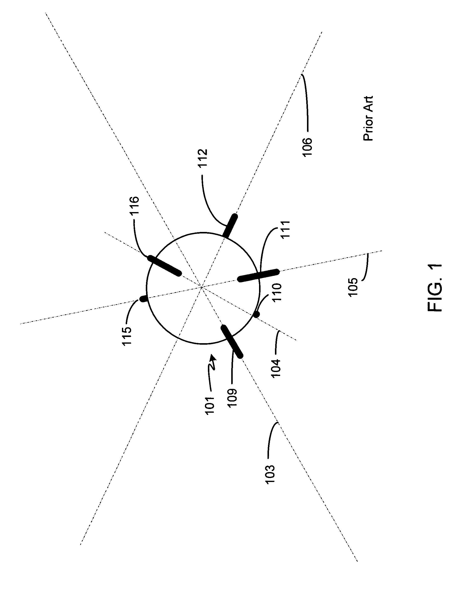
[0028]FIG. 1 is an illustration of a spherical sonoluminescence cavitation chamber 101, hereafter referred to as simply a cavitation chamber, according to the prior art. Transducers 109–112 are mounted to the lower hemisphere of chamber 101 and transducers 115–116 are mounted to the upper hemisphere of chamber 101.

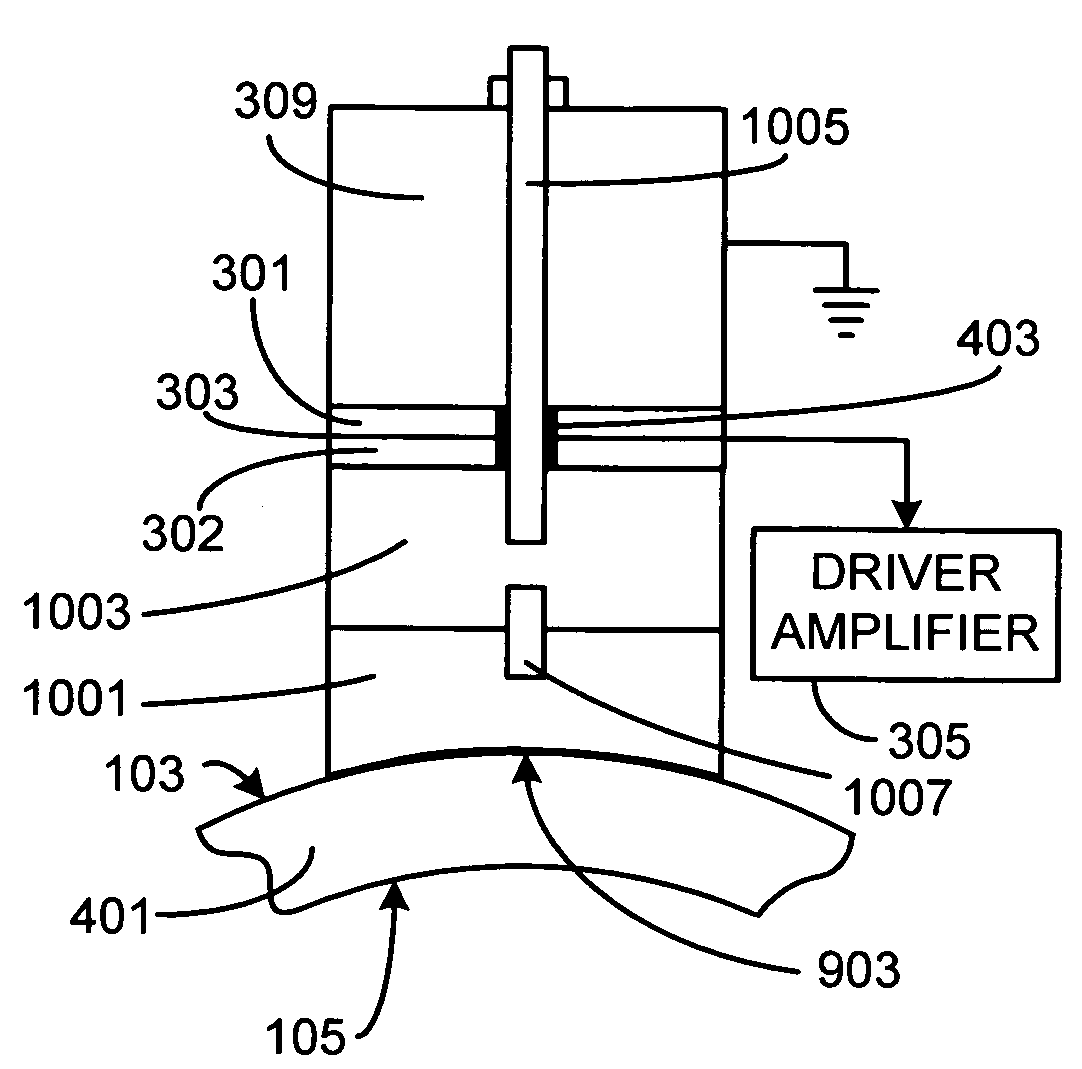
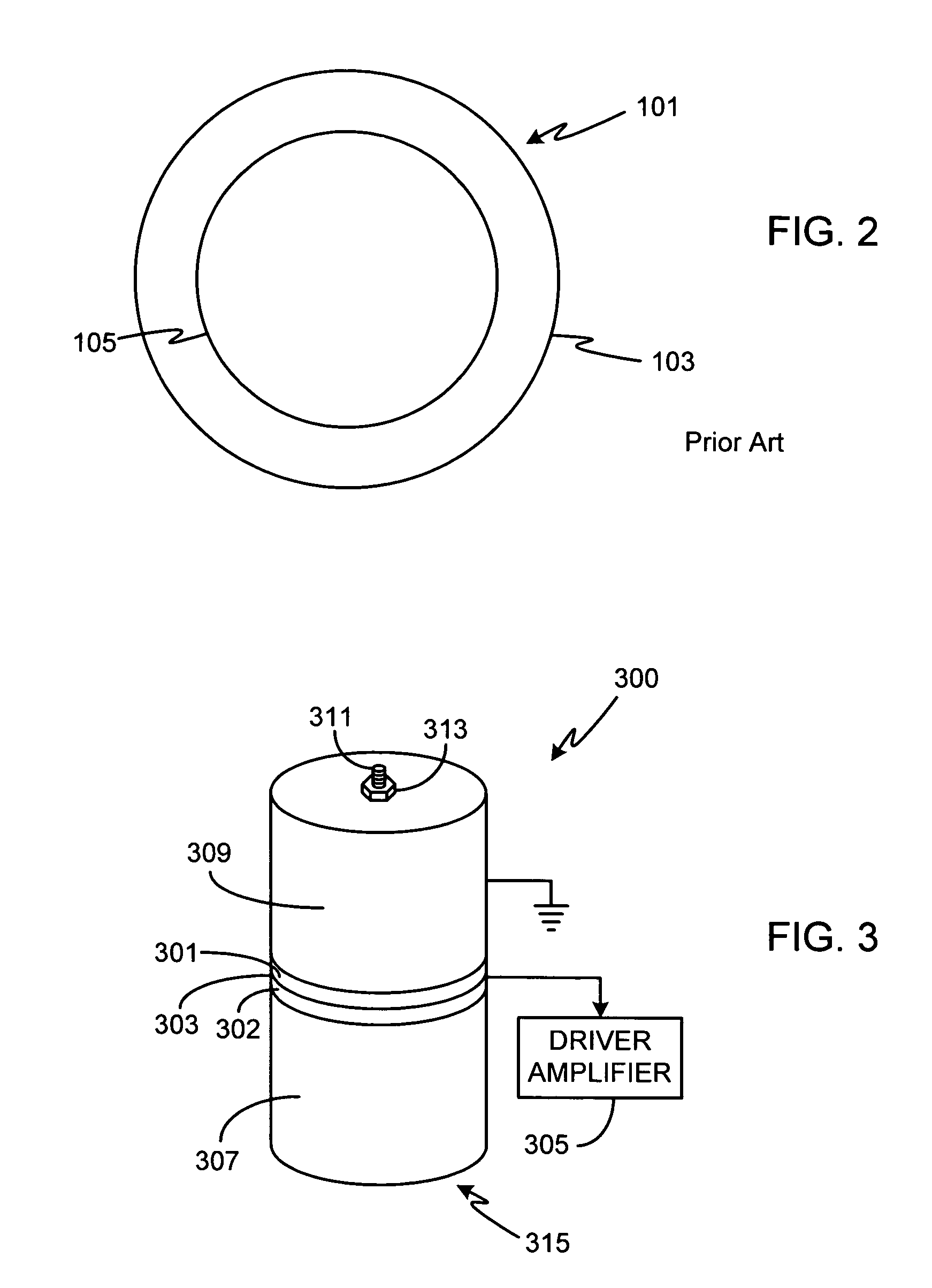
[0029]FIG. 2 is a cross-sectional view of spherical cavitation chamber 101. Chamber 101 has an outer spherical surface 103 defining the outer diameter of the chamber, and an inner spherical surface 105 defining the inner diameter of the chamber. The fabrication of a spherical chamber is described in detail in co-pending application Ser. No. 10 / 925,070, filed Aug. 23, 2004, entitled Method of Fabricating a Spherical Cavitation Chamber, the disclosure of which is incorporated herein for any and all purposes.

[0030]Chamber 101 can be fabricated from any of a variety of materials, depending primarily on the desired operating temperature and pressure, as well as the fabrication ...


PUM


Abstract

An acoustic driver assembly for use with a spherical cavitation chamber is provided. The acoustic driver assembly includes at least one transducer, a head mass and a tail mass, coupled together with a centrally located threaded means (e.g., all thread, bolt, etc.). The driver assembly is permanently attached to the exterior surface of the spherical cavitation chamber via brazing or diffusion bonding. In at least one embodiment, the transducer is comprised of a pair of piezo-electric transducers, preferably with the adjacent surfaces of the piezo-electric transducers having the same polarity. The surface of the head mass that is adjacent to the external surface of the chamber has a spherical curvature equivalent to the spherical curvature of the external surface of the chamber, thus providing maximum coupling efficiency between the acoustic driver and the cavitation chamber. In at least one embodiment a void filling material is interposed between one or more pairs of adjacent surfaces of the driver assembly.

Description

REFERENCE TO RELATED APPLICATIONS[0001]This application is a continuation of U.S. patent application Ser. No. 10 / 931,918, filed Sep. 1, 2004.FIELD OF THE INVENTION[0002]The present invention relates generally to sonoluminescence and, more particularly, to an acoustic driver assembly for use with a sonoluminescence cavitation chamber.BACKGROUND OF THE INVENTION[0003]Sonoluminescence is a well-known phenomena discovered in the 1930's in which light is generated when a liquid is cavitated. Although a variety of techniques for cavitating the liquid are known (e.g., spark discharge, laser pulse, flowing the liquid through a Venturi tube), one of the most common techniques is through the application of high intensity sound waves.[0004]In essence, the cavitation process consists of three stages; bubble formation, growth and subsequent collapse. The bubble or bubbles cavitated during this process absorb the applied energy, for example sound energy, and then release the energy in the form of...

Claims


Application Information

Patent Timeline
Patent Type & Authority Patents(United States)
IPC IPC(8): B06B1/06H01L41/08G10K15/04
CPCG10K15/043
Inventor TESSIEN, ROSS ALANGAITAN, DARIO FELIPEPHILLIPS, DANIEL A.
Owner BURST ENERGIES INC
Why Eureka
Try Eureka