Optical connection component

a technology of optical connection and component, applied in the direction of optical elements, semiconductor lasers, instruments, etc., can solve the problems of reducing the tolerances of positioning the optical fiber, the fundamental physical limitations of the electrical connection for high-speed data transmission, and the cumbersome and expensive precision of the positioning of the optical fiber, so as to achieve the effect of reducing the number of coupling losses and avoiding substantial coupling losses

Inactive Publication Date: 2012-06-12
EDITH COWAN UNIV +1
View PDF27 Cites 14 Cited by
  • Summary
  • Abstract
  • Description
  • Claims
  • Application Information

AI Technical Summary

Benefits of technology

[0017]The optical connection component has significant practical advantages. Due to the optical lens, divergence of the beam of laser light is reduced and consequently the exact positioning of the optical waveguide, such as an optical fibre, is less critical. As a consequence, packaging tolerances are increased and the cost of manufacture is reduced. Further, as the optical lens is immobile relative to the solid state laser component and positioned at the predetermined position, adjustment of the lens is avoided which also reduces the cost of production.
[0064]wherein the first predetermined position is selected so that the modulated light can be coupled from the solid state laser component into the optical fibre without substantial coupling losses and the second predetermined positions is selected so that the modulated light can be coupled from the optical fibre into the receiver without substantial coupling losses.

Problems solved by technology

However, electrical connects have fundamental physical limitations for high speed data transmission, which relate to electrical power requirements, transmission latency, achievable package density, etc.
Key issues for designing OI's having a low Bit-Error Rate (BER) are transmission distance, properties of the optical waveguide such as dispersion, coupling losses, and properties of the optical source and receiver.
However, for short optical links between chips losses of the optical waveguide and dispersion of guided light are negligible and consequently the remaining key-issues for the design of an OI are the properties of the source, the properties of the receiver and the coupling between them.
Such precise positioning of the optical fibre is cumbersome and expensive.
Such smaller core diameters reduce the tolerances in positioning the optical fibre even further, which results in a significant technological challenge.

Method used


Image

  • Optical connection component
  • Optical connection component
  • Optical connection component

Examples


Embodiment Construction

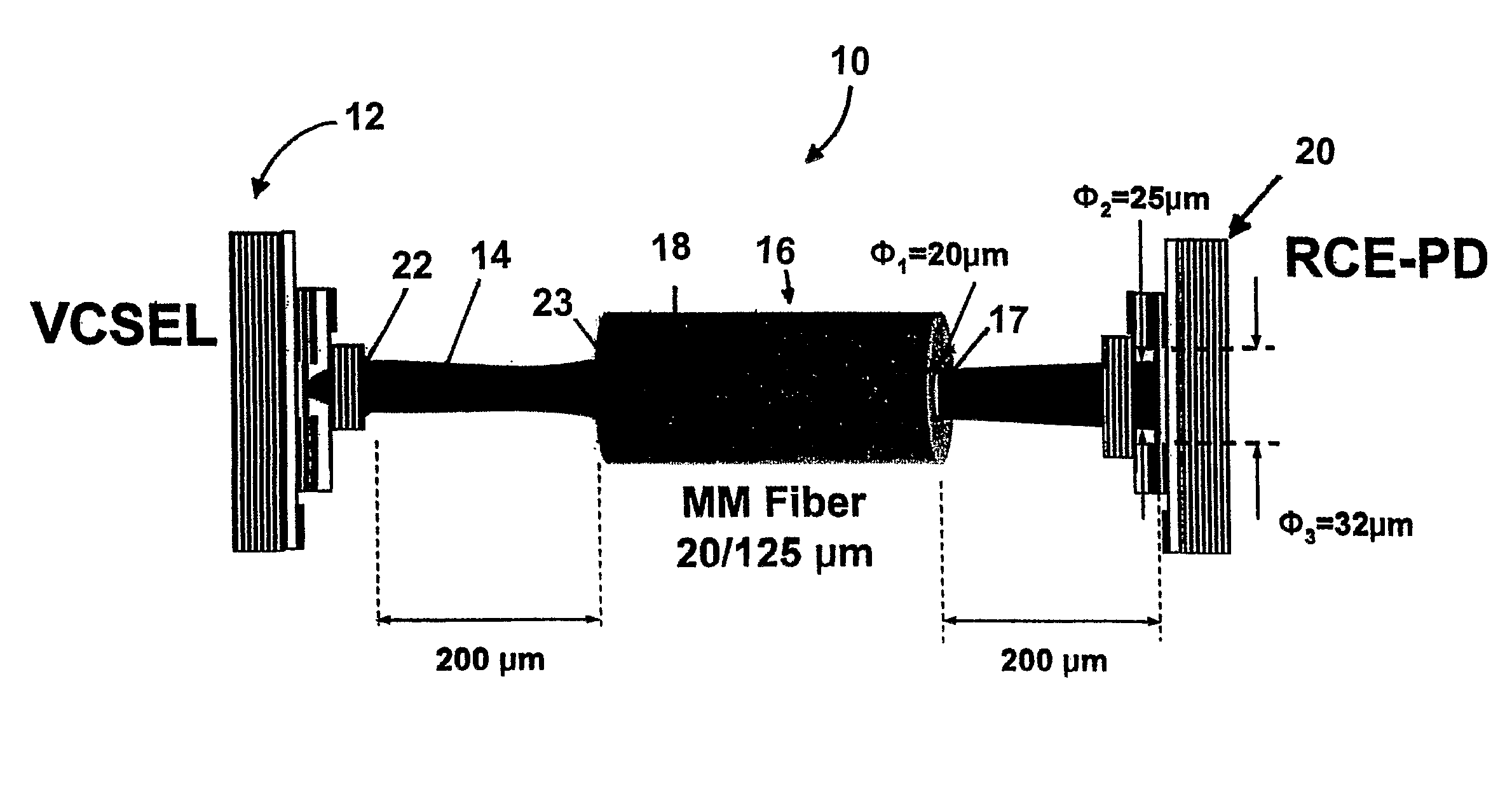
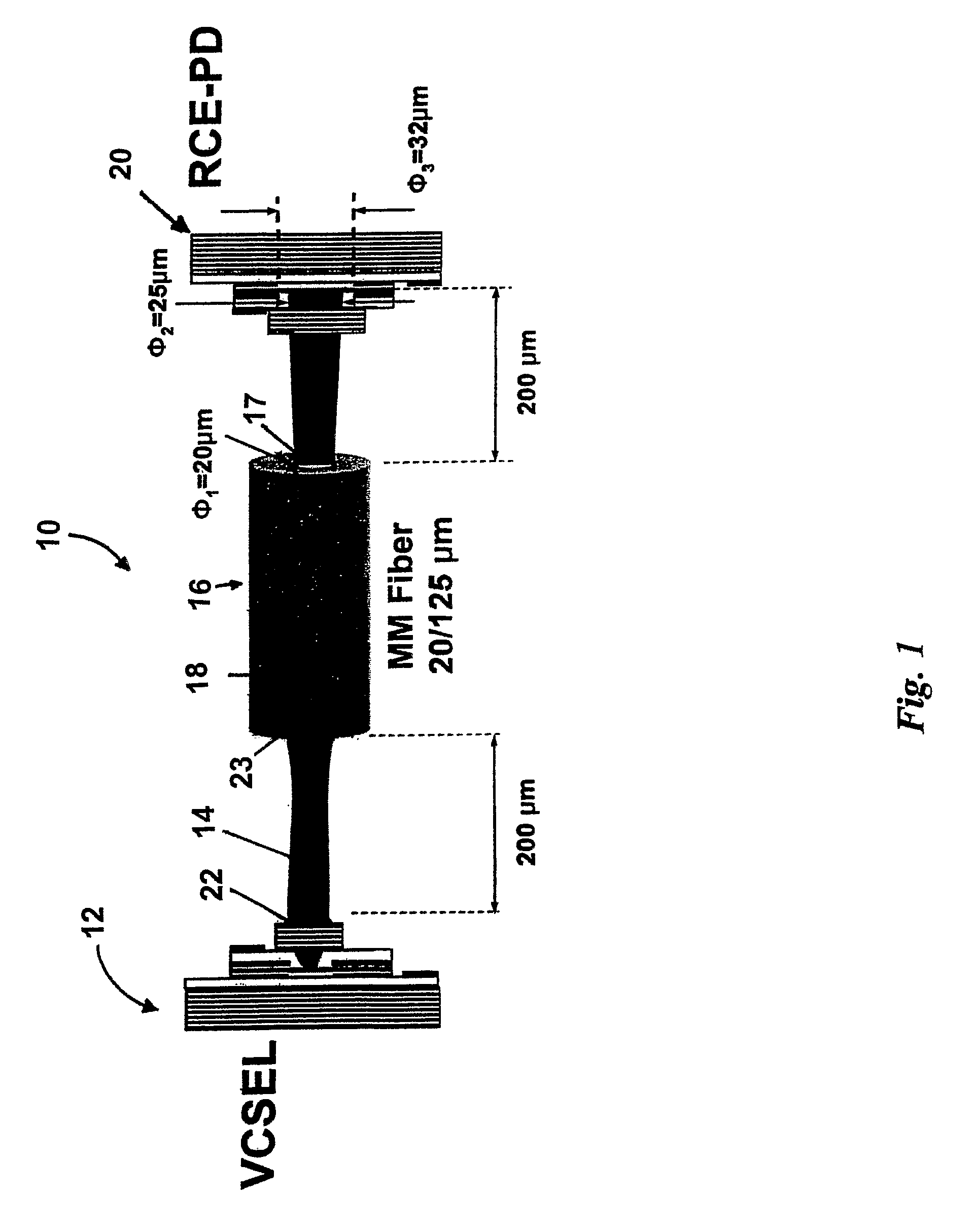
[0085]Referring initially to FIG. 1, an optical connection component according to a specific embodiment of the present invention is now described. The optical connection component 10 comprises a solid state laser component, which is in this embodiment provided in the form of a vertical cavity surface emitting laser (VCSEL) 12. The VCSEL 12 emits laser light 14, which is coupled into an optical fibre 16. The optical fibre 16 guides the emitted light in a core 18. The guided light is emitted from an end-portion 17 of the optical fibre 16 and directed to a receiver, which is in this embodiment provided in the form of a resonant cavity enhanced photo diode (RCE-PD) 20.

[0086]The optical connection component 10 comprises input terminals (not shown) to which an electrical signal is applied and which are connected to the VCSEL 12 so that the emitted laser beam 14 is modulated by the electrical signal. The high frequency electrical signal is in this example associated with transmission of da...


PUM


Abstract

The present invention provides an optical connection component which comprises a solid state laser component for emitting a modulated beam of light in response to an applied electrical signal. The optical connection component also comprises an optical lens positioned relative to the solid state laser component at a predetermined position in which the optical lens reduces divergence of the emitted beam of light. The optical lens is formed at the predetermined position in a manner such that the optical lens is immobile relative to the solid state laser component. The optical connection component further comprises an optical waveguide having a core for guiding the light. The optical waveguide has first and second end-portions. The first end-portion is positioned for coupling the modulated light from the optical lens into the core. In addition, the optical connection component comprises a receiver for receiving the modulated light from the second end-portion of the optical waveguide and arranged for converting the modulated light into a corresponding electrical signal.

Description

CROSS REFERENCE TO RELATED APPLICATIONS[0001]This application is being filed under 35 U.S.C. 371 as a United States National Phase application of International Patent Application Number PCT / AU2006 / 001992, filed Dec. 22, 2006, which claims priority to Australian patent application number 2006905043, filed Sep. 13, 2006 all of which are hereby incorporated by reference as if listed in their entirety herein for all purposes.FIELD OF THE INVENTION[0002]The present invention broadly relates to an optical connection component. The present invention relates particularly, though not exclusively, to an optical connection system for transmission of data at a capacity of a few Gb / s or more.BACKGROUND OF THE INVENTION[0003]Today's large-scale multiprocessor computer systems include hundreds of CPUs and data storage devices having terabytes of memory. Data transmission between processors requires wide bandwidths and a data transmission speed of few Tb / s may be required by the end of this decade....

Claims


Application Information

Patent Timeline
Patent Type & Authority Patents(United States)
IPC IPC(8): G02B6/36G02B6/42H01S5/026
CPCG02B6/4204H04B10/25G02B6/42
Inventor LEE, YONG TAKALAMEH, KAMAL
Owner EDITH COWAN UNIV
Why Eureka
Try Eureka