Method of forming a hard bias structure in a magnetic head
a magnetic head and hard bias technology, applied in nanoinformatics, instruments, record information storage, etc., can solve the problems of loss of sensor stability, reduced sensor amplitude, and inability to produce sufficient biasing efficiency of abj-hb configuration
- Summary
- Abstract
- Description
- Claims
- Application Information
AI Technical Summary
Benefits of technology
Problems solved by technology
Method used
Image
Examples
second embodiment
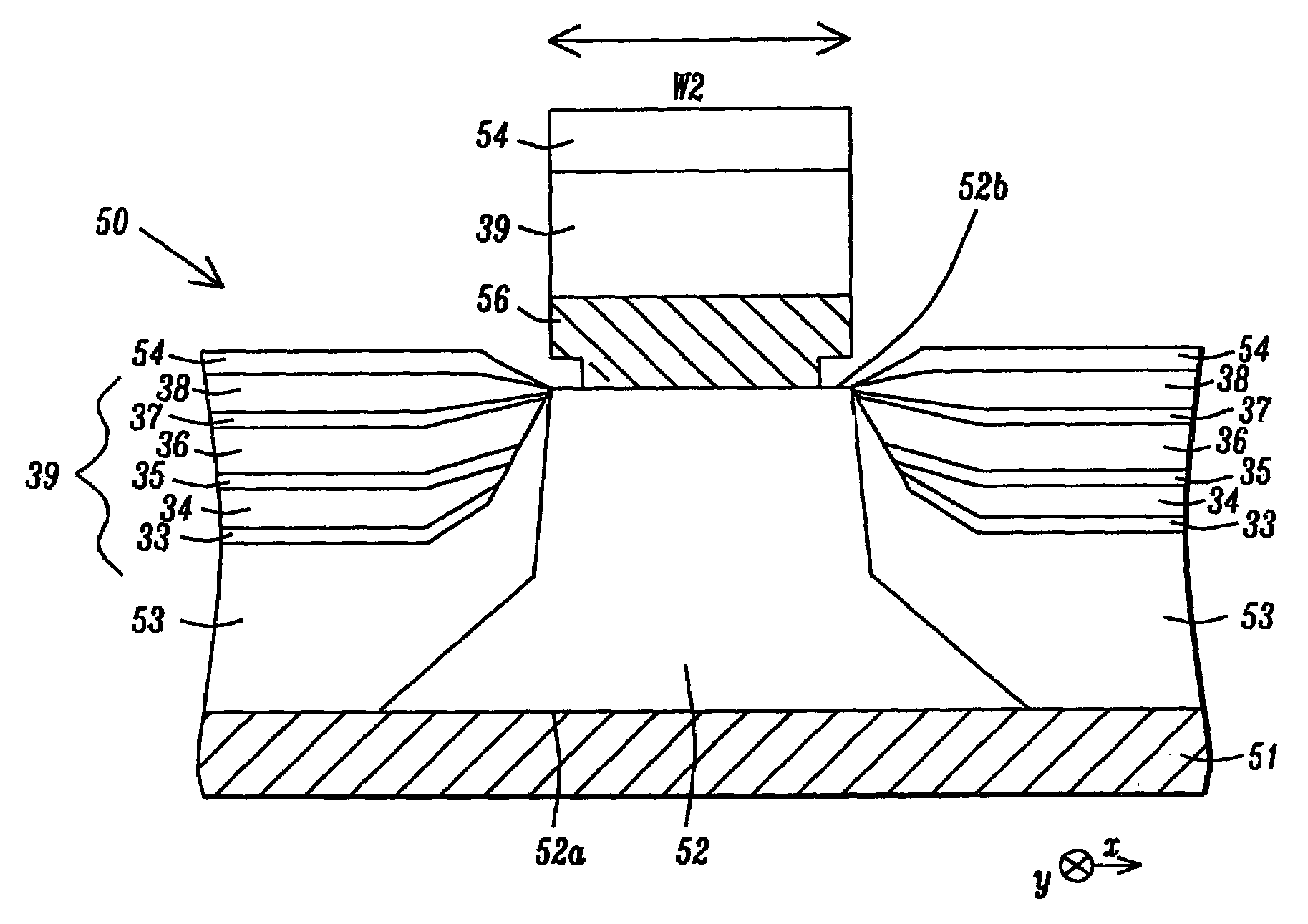
[0038]The present invention is a hard bias configuration comprised of a main biasing layer with a high negative magnetostriction value (λS) that improves the performance of a magnetic read head based on a magnetoresistive (MR) sensor element. Although the exemplary embodiments describe GMR-CIP, GMR-CPP, or TMR sensors having a single spin valve, those skilled in the art will appreciate that the present invention may also apply to multilayer sensor designs based on a GMR, TMR, or spin valve magneto-resistive (SVMR) effect. The drawings are provided by way of example and are not intended to limit the scope of the invention. For example, the shape of a MR element in a magnetic device is not a limitation and the present invention encompasses any configuration wherein a hard bias stack as described in the first or second embodiment maintains a single magnetic domain in a free layer within the MR sensor element. Moreover, the MR sensor element may be comprised of either a top spin valve o...
first embodiment
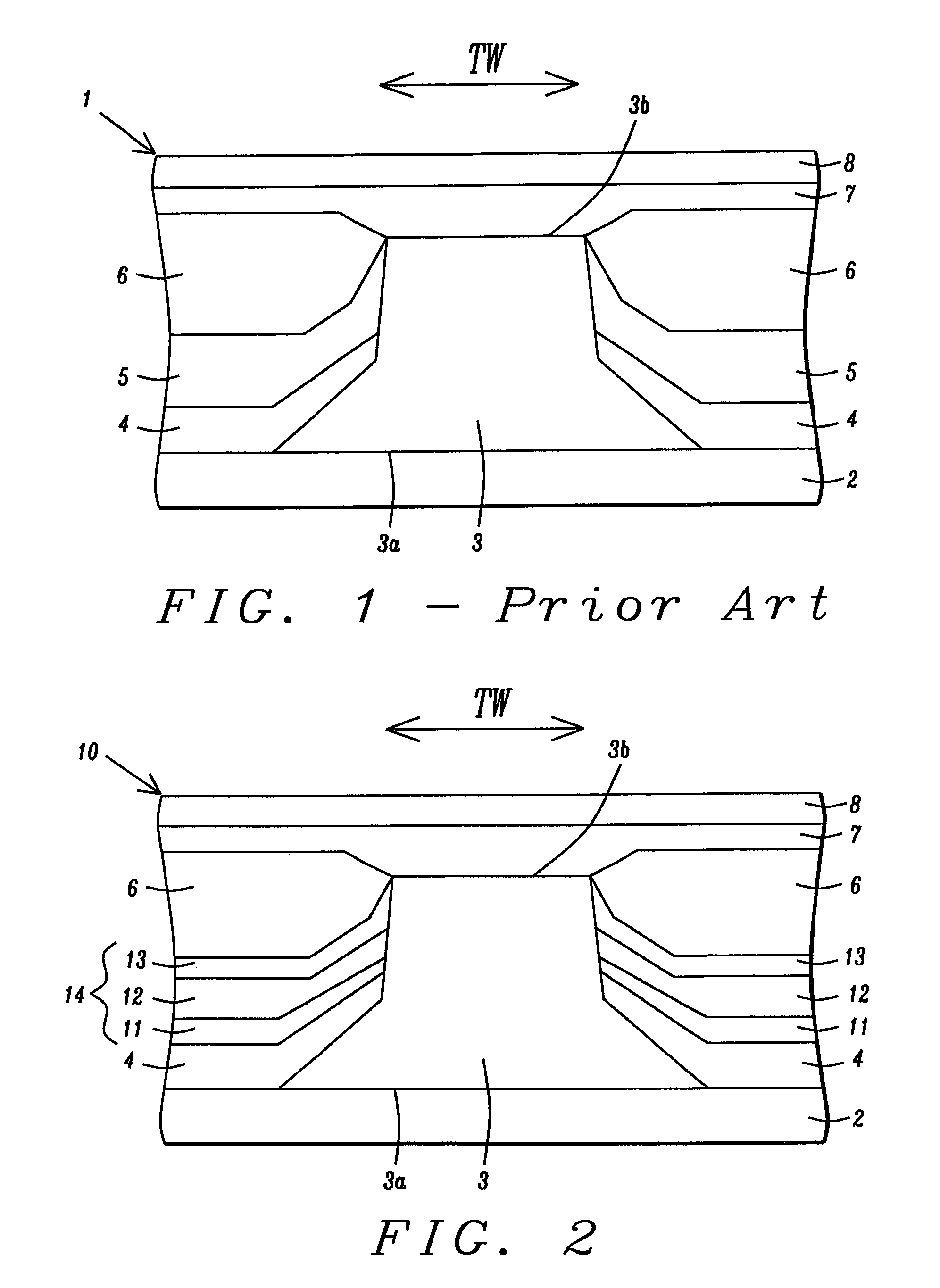
[0042]the present invention is depicted in FIGS. 6-7. Referring to FIG. 6, a cross-sectional view from an ABS plane is shown of a magnetic read head 30 formed on a substrate 31. In one embodiment, the sensor element 32 is a GMR-CIP spin valve and the substrate 31 is a first gap layer such as Al2O3 that is disposed on a first shield (not shown). The sensor element 32 is a stack of layers comprised of an AFM layer, an overlying (or underlying) pinned layer, a free layer, a non-magnetic conductive spacer between the pinned and free layers, and an uppermost capping layer. The arrangement of the layers in the stack is dependent on whether the sensor element 32 is a bottom spin valve or top spin valve type. Note that the individual layers within the sensor element 32 are not shown in order to simplify the drawing and direct attention to the adjacent ABJ-EX hard bias structure 39. Typically, the layers within the sensor element 32 have top and bottom surfaces that are parallel to the botto...
PUM
| Property | Measurement | Unit |
|---|---|---|
| thickness | aaaaa | aaaaa |
| thickness | aaaaa | aaaaa |
| thickness | aaaaa | aaaaa |
Abstract
Description
Claims
Application Information
 - R&D
- Intellectual Property
- Life Sciences
- Materials
- Tech Scout
- Unparalleled Data Quality
- Higher Quality Content
- 60% Fewer Hallucinations
Browse by: Latest US Patents, China's latest patents, Technical Efficacy Thesaurus, Application Domain, Technology Topic, Popular Technical Reports.
© 2025 PatSnap. All rights reserved.Legal|Privacy policy|Modern Slavery Act Transparency Statement|Sitemap|About US| Contact US: help@patsnap.com


