Spring and manufacture method thereof

a technology of fatigue resistance and spring, which is applied in the field of springs with superior fatigue resistance, can solve the problems of difficult to remove tensile residual stress, limit the increase of anneal softening resistance, etc., and achieve the effects of reducing fatigue resistance, reducing compressive residual stress obtained by shot peening, and large permanent s

Active Publication Date: 2014-01-09
NHK SPRING CO LTD
View PDF7 Cites 3 Cited by
  • Summary
  • Abstract
  • Description
  • Claims
  • Application Information

AI Technical Summary

Benefits of technology

[0038]In the strain aging step of the present invention, a spring is preferably heated at a temperature of 150 to 300° C. for 10 minutes or more. If the heating temperature is less than 150° C., movement of C is not sufficient and the dislocation is not sufficiently fixed, and amount of permanent set is large. If the heating temperature is more than 300° C., the compressive residual stress obtained by the shot peening is decreased, and fatigue resistance is decreased. If the heating time is less than 10 minutes, movement of C is not sufficient and the dislocation is not sufficiently fixed, and amount of permanent set is large. Even if the heating time is more than 60 minutes, effect of fixing dislocation is saturated. Therefore, the heating time is preferably 60 minutes for production efficiency and cost.
[0039]The setting step is performed by providing plastic strain to a material so as to improve the elastic limit and to decrease the amount of amount of permanent set (sag). In the setting step, the spring is preferably heated at a temperature of 150 to 300° C. and share strain of 0.015 to 0.022 is generated on a surface of the wire material. The setting step is performed for obtaining the same effect of the strain aging step. The setting is performed at the same temperature (150 to 300° C.) in the strain aging, whereby sag resistance is

Problems solved by technology

On the other hand, the material is softened through annealing and there is limitation for increase of anneal softening res

Method used


Image

  • Spring and manufacture method thereof
  • Spring and manufacture method thereof

Examples


examples

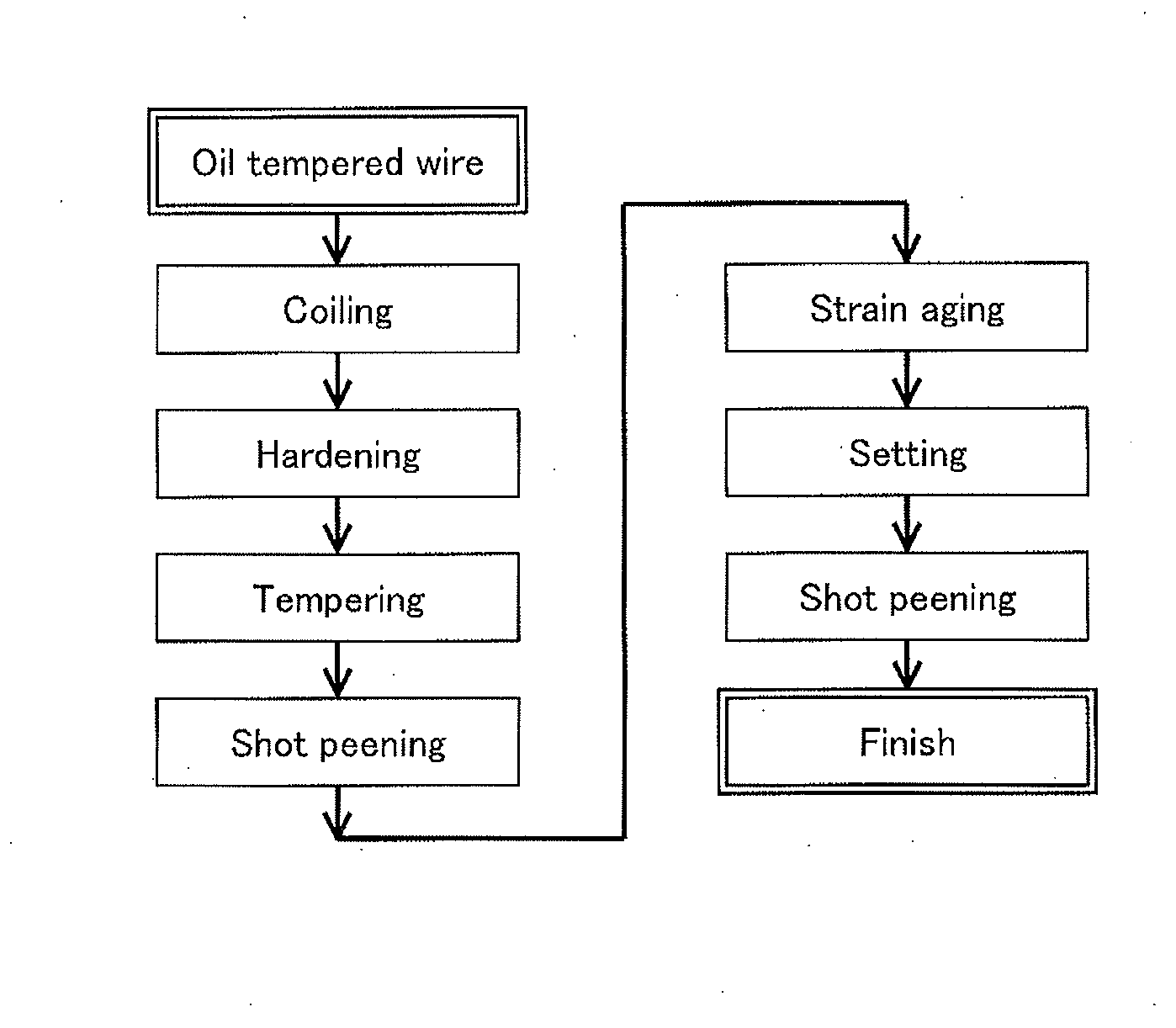
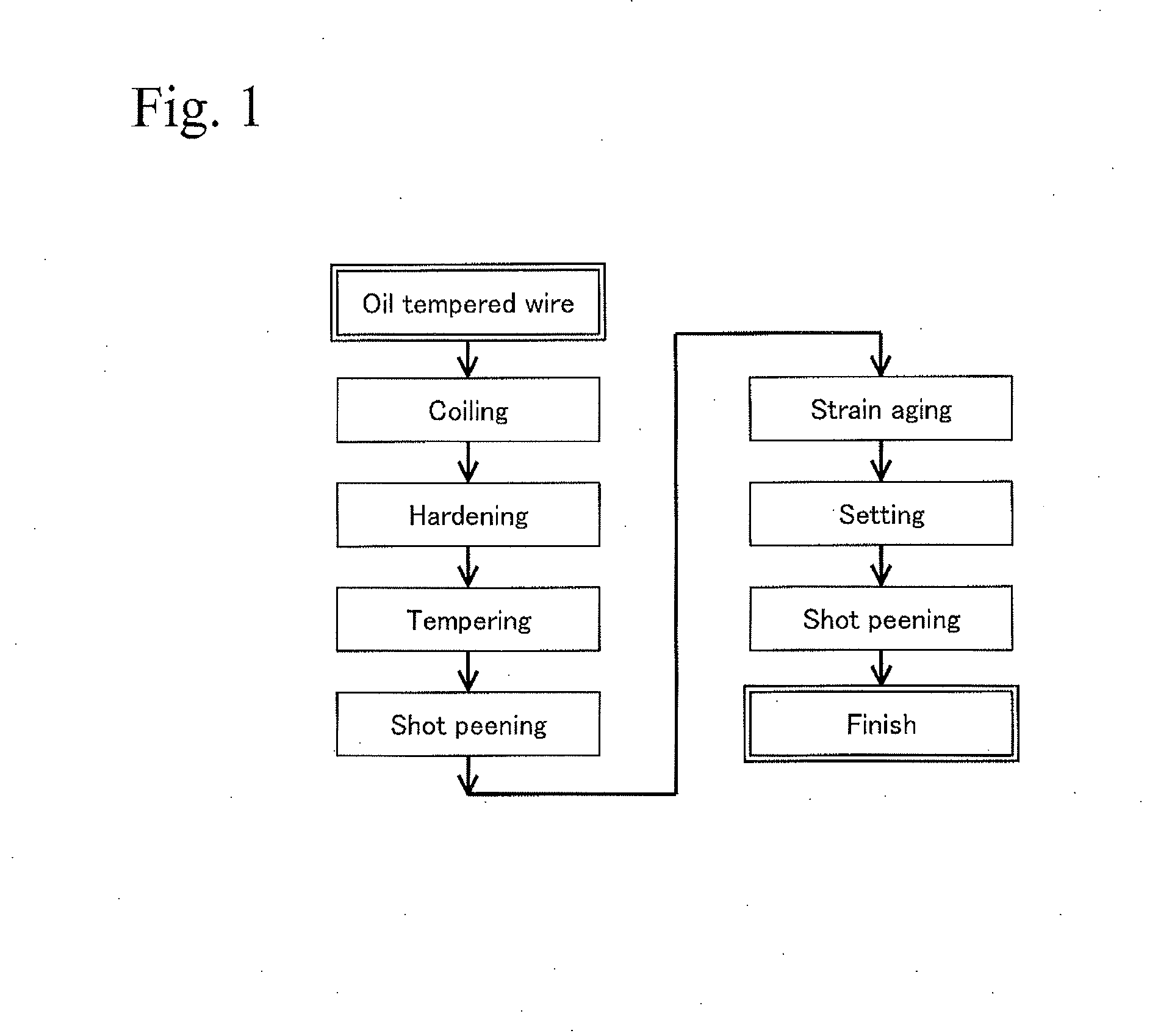
[0049]Springs were produced according to the steps shown in FIG. 1. That is, an oil tempered wire (SWOSC-V) having a composition shown in Table 1 was prepared and was cold coiled into a predetermined shape by a coiling machine, whereby springs shown in Table 2 were obtained. The springs were subjected to a heat treatment at a condition shown in Table 3. Next, the springs were subjected to shot peening. In the shot peening, round cut wires with a sphere-equivalent diameter of 0.8 mm were used in a first step. Then, round cut wires with a sphere-equivalent diameter of 0.45 mm were used in a second step. Moreover, the springs were heated to 230° C. for 10 minutes for strain aging and were cooled down to room temperature. Then, the springs were subjected to cold setting corresponding to maximum shear strain of 0.020 (maximum shear stress of τ=1565 MPa, and modules of rigidity of 78.5 GPa). Various characteristics of the springs were investigated in the following manner with respect to t...


PUM

PropertyMeasurementUnit
Temperatureaaaaaaaaaa
Lengthaaaaaaaaaa

Abstract

A spring with superior fatigue resistance is provided by decreasing the material cost while simplifying the production process. Disclosed is a spring including: a composition consisting of, by mass %, 0.5 to 0.7% of C, 1.0 to 2.0% of Si, 0.1 to 1.0% of Mn, 0.1 to 1.0% of Cr, not more than 0.035% of P, not more than 0.035% of S, and the balance of Fe and impurities; a structure including not less than 95% of tempered martensitic structure; a compressive residual stress layer formed to a depth of 0.35 mm to D/4, in which D (mm) is a diameter; the compressive residual stress layer having maximum compressive residual stress of 800 to 2000 MPa; a center portion with Vickers hardness of 550 to 700 HV; and a high hardness layer with greater hardness than the center portion.

Description

TECHNICAL FIELD[0001]The present invention relates to a spring with superior fatigue resistance, and relates to a production method therefor.BACKGROUND ART[0002]For example, materials for valve springs for automobile engines may include oil tempered carbon steel wires (SWO-V), oil tempered chromium-vanadium steel wires (SWOCV-V), and oil tempered chromium-silicon steel wires (SWOSC-V), which are specified in the Japanese Industrial Standards (JIS). The oil tempered chromium-silicon steel wires are conventionally widely used in view of the fatigue resistance and the sag resistance. In recent years, reduction in weight of the valve spring is strongly desired in order to improve fuel efficiency of automobiles, and there is a trend of increasing tensile strength in spring wire so as to increase design stress of the valve spring. In a case of a spring wire such as an oil tempered wire specified in the JIS, notch sensitivity to cracks and defects such as inclusions is greatly increased ac...

Claims


Application Information

Patent Timeline
IPC IPC(8): F16F1/02
CPCF16F1/021B21F35/00C21D7/06C21D9/02C22C38/02C22C38/04C22C38/18C21D2211/008C22C38/34Y10T29/49609F16F1/06
Inventor SUZUKI, TAKESHIONO, YOSHIKIKUROKAWA, SHIMPEI
Owner NHK SPRING CO LTD
Why Eureka
Try Eureka