Method of Constrained Aggressor Set Selection for Crosstalk Induced Noise

Inactive Publication Date: 2009-03-19
IBM CORP
View PDF15 Cites 13 Cited by
  • Summary
  • Abstract
  • Description
  • Claims
  • Application Information

AI Technical Summary

Benefits of technology

[0010]It is a primary object of the invention to provide a system and a method for efficiently c

Problems solved by technology

In addition, due to the increase in the design complexity, wires are brought closer to each other.
In addition, coupling also causes erroneous or false switchings which may lead to functional failures in a circuit.
It should be added that due to the increase in design complexity and wires' current density, inductive coupling effects on timing are becoming critical.
Timing analysis considering coupling events is therefore, unavoidable.
The noise bump can potentially change the logic value at 104 and cause a functional failure.
This change is often termed coupling induced delay push-out and can cause delay failures in the chip.
Referring back to FIG. 1a, and focusing on the timing impact of the coupling induced noise first, a significant drawback of the prior mentioned coupling analysis method is illustrated using an example o

Method used


Image

  • Method of Constrained Aggressor Set Selection for Crosstalk Induced Noise
  • Method of Constrained Aggressor Set Selection for Crosstalk Induced Noise
  • Method of Constrained Aggressor Set Selection for Crosstalk Induced Noise

Examples


Embodiment Construction

[0024]The present invention and the various features and advantageous details thereof are explained more fully with reference to the non-limiting embodiments that are illustrated in the accompanying drawings and detailed in the following description. It should be noted that the features illustrated in the drawings are not necessarily drawn to scale. Descriptions of well-known components and processing techniques are omitted so as to not unnecessarily obscure the present invention in detail.

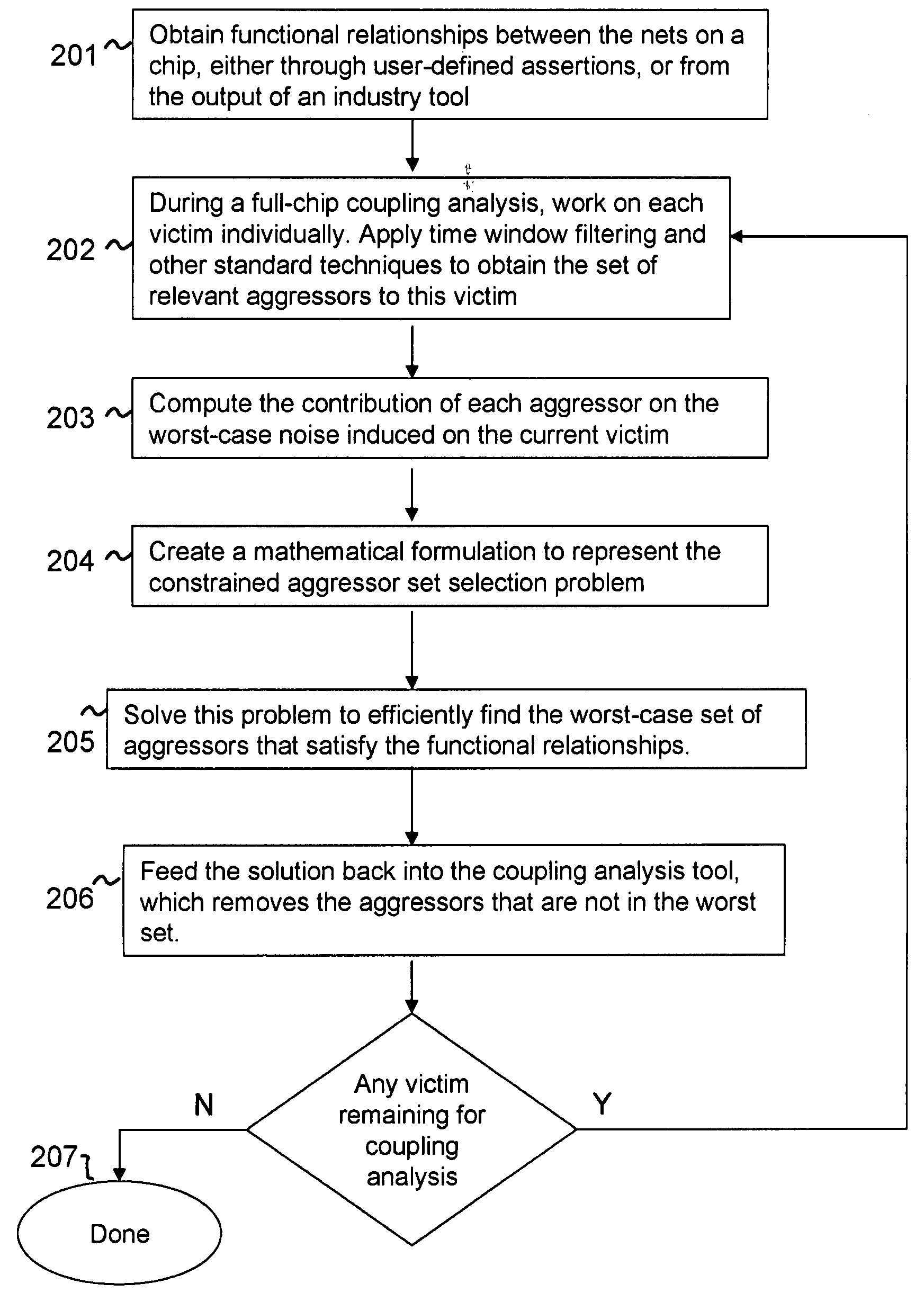
[0025]Referring to FIG. 2, there is shown a method for computing the worst feasible set of aggressors of a victim according to the present invention. Hereinafter are described solutions for a capacitively coupled set of nets. These solutions can advantageously be extended to include inductive coupling, as will be explained later.

[0026]In block 201 functional relationships between nets in a chip is obtained. This can be determined using industry standard functional analysis tools or asserted by the...


PUM


Abstract

A preliminary static timing analysis run is performed to calculate the delay and slew as well as timing windows for each net in the design, followed by coupling analysis for each given aggressor-victim combination, and to calculate the noise effect on the timing of victim net. Given a set of functional groups that relate the coupled aggressors to each other, the worst set of aggressors are calculated that satisfy the constraints from the functional groups, based on the calculated impact of each aggressor on the victim. Similarly the set of aggressors which contribute to the maximum amount of inductive coupling noise effect on timing are calculated. Furthermore, the coupling noise impact of the reduced set of aggressors on the given victim line and adjust the delay value calculated in the preliminary static timing analysis run.

Description

FIELD OF THE INVENTION[0001]This invention generally relates to the field of Design Automation, and more particularly, to a system and a method of calculating the impact of coupling noise on static timing and false switching of integrated circuits considering logical constraints between aggressor lines.BACKGROUND OF THE INVENTION[0002]Static timing analysis (STA) is an essential step in the design of high speed very large scale integrated (VLSI) circuits. STA verifies that a VLSI chip will perform correctly at a required frequency before it is released for manufacturing.[0003]Neighboring wires in a chip induce capacitive coupling effects (hereinafter also referred to crosstalk) on each other. As CMOS technology scales down, wires inside a chip become taller and thinner. In addition, due to the increase in the design complexity, wires are brought closer to each other. These, altogether, amplify the ratio of the coupling capacitance between the wires to their corresponding grounded ca...

Claims


Application Information

Patent Timeline
IPC IPC(8): G06F17/50
CPCG06F17/5036G06F30/367
Inventor SINHA, DEBJITABBASPOUR, SOROUSHAKHTER, AYESHASCHAEFFER, GREGORY M.WIDIGER, DAVID J.
Owner IBM CORP
Why Eureka
Try Eureka