Power supply apparatus
a technology of power supply apparatus and power supply device, which is applied in the direction of power conversion system, dc-dc conversion, instruments, etc., to achieve the effect of high speed response and easy design
- Summary
- Abstract
- Description
- Claims
- Application Information
AI Technical Summary
Benefits of technology
Problems solved by technology
Method used
Image
Examples
first embodiment
1. First Embodiment
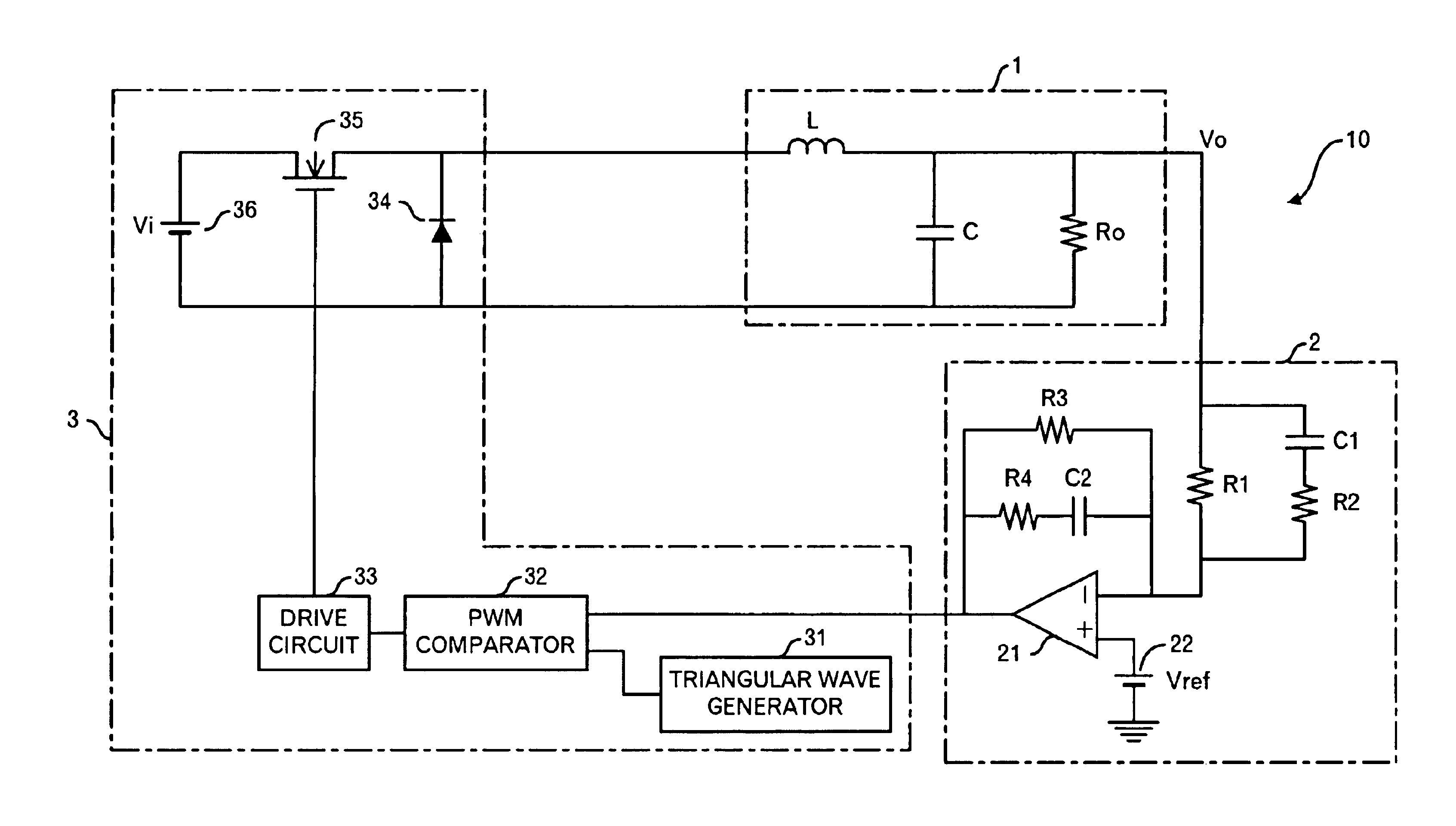
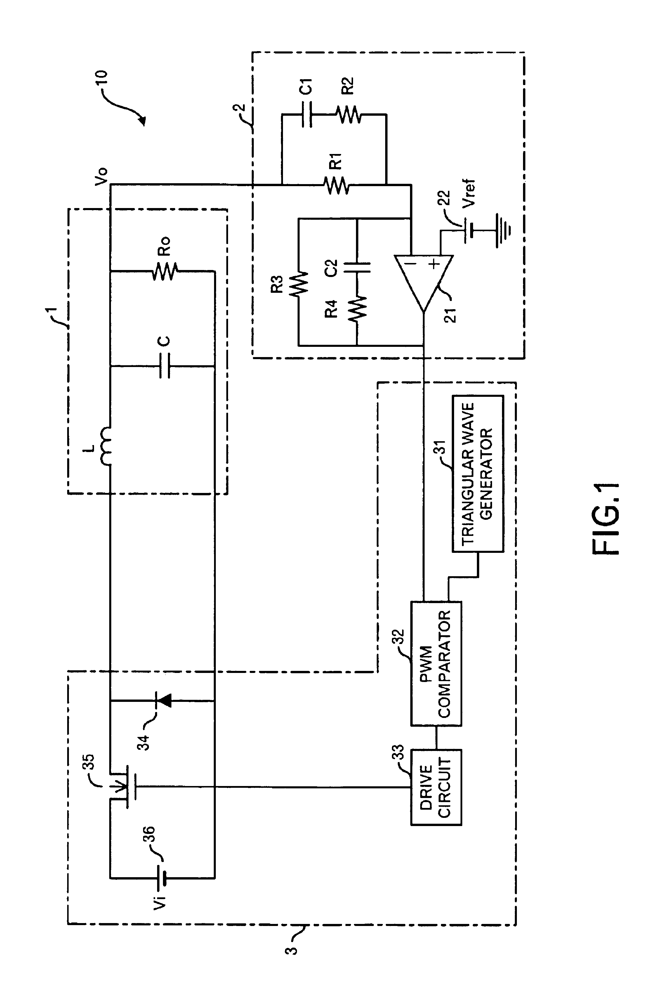
[0043]FIG. 1 shows the circuit structure of a power supply apparatus 10 according to the first embodiment of this invention. The power supply apparatus 10 is a power supply apparatus of a step-down type, and it is composed of a LC filter 1, controller 2 that is a PID controller, and power converter 3.
[0044]The controller 2 includes resistors R1 to R4, capacitors C1 and C2, an amplifier 21, and a reference voltage power supply 22. The resistor R1 and capacitor C1 are connected to a positive terminal of a load Ro in the LC filter 1. That is, an output voltage Vo is input to the controller 2. The capacitor C1 and resistor R2 are connected in series, and the capacitor C1 and resistor R2 are connected to the resistor R1 in parallel. Therefore, one terminal of the resistor R1 whose another terminal connects to the capacitor C1 is connected with the resistor R2. Moreover, the resistor R1 and R2 are connected to a negative input terminal (i.e. an inversion input terminal)...
second embodiment
2. Second Embodiment
[0065]The circuit structure of a power supply apparatus 20 according to this embodiment is shown in FIG. 11. The differences with the power supply apparatus 10 shown in FIG. 1 are a point in which a resistor Rc is connected to the capacitor C of the LC filter 1b in series, and a point in which the circuit constants of the resistors and capacitors in the controller 2b are changed as shown in FIG. 12. Therefore, its connection is not explained here. Incidentally, the resistor Rc is called an equivalent series resistance, and represents a resistance component included in the capacitor C. Therefore, Rc is about 2 mΩ. As explained later, the resistor Rc functions as a phase-lead compensation element in the high frequency range. The circuit constants of the resistors and the capacitors in the controller 2b are R1=1 kΩ, R2=60Ω, R3=430 kΩ, R4=1.4 kΩ, C1=3.3 nF, and C2=1.8 nF as shown in FIG. 12.
[0066]When the transfer function of the controller 2b is calculated, the foll...
third embodiment
3. Third Embodiment
[0072]There is no difference in the number of resistors and capacitors and the connection between the controller 2 in the first embodiment and the controller 2b in the second embodiment, though the circuit constants are different. In the third embodiment, the circuit shown in FIG. 16 is adopted instead of the controller 2 or the controller 2b.
[0073]That is, it is a circuit in which the resistor R3 in the controller 2 or the controller 2b shown in FIG. 1 or FIG. 11 is detached. More specifically, the controller 2c includes resistors R1, R2 and R4, capacitors C1 and C2, an amplifier 21, and a reference voltage power supply 22. The resistor R1 and capacitor C1 are connected to the positive polarity side terminal of the load Ro of the LC filter 1. The capacitor C1 and resistor R2 are connected in series, and the capacitor C1 and resistor R2 are connected to the resistor R1 in parallel. Therefore, one terminal of the resistor R1 whose another terminal is connected to ...
PUM
 Abstract
Description
Claims
Application Information
 - R&D
- Intellectual Property
- Life Sciences
- Materials
- Tech Scout
- Unparalleled Data Quality
- Higher Quality Content
- 60% Fewer Hallucinations
Browse by: Latest US Patents, China's latest patents, Technical Efficacy Thesaurus, Application Domain, Technology Topic, Popular Technical Reports.
© 2025 PatSnap. All rights reserved.Legal|Privacy policy|Modern Slavery Act Transparency Statement|Sitemap|About US| Contact US: help@patsnap.com


