High-accuracy 1X variable-reluctance resolver

a resolution and variable resistance technology, applied in the direction of converting the output of the sensor electrically/magnetically, linear/angular speed measurement, instruments, etc., can solve the problems of large output signal voltage errors, deterioration in accuracy compared with the design output voltage signal, etc., and achieve high accuracy and simple structure

Inactive Publication Date: 2005-10-25
MINEBEA CO LTD
View PDF5 Cites 12 Cited by
  • Summary
  • Abstract
  • Description
  • Claims
  • Application Information

AI Technical Summary

Benefits of technology

[0017]An object of the present invention is to provide a high-accuracy, 1X VR resolver which has a simple structure and which can output a high accuracy rotational angle signal whose shaft angle multiplier is 1X.
[0027]The VR resolver of the present invention has a rotor and a stator. The rotor is formed through axial connection of a first rotor portion and a second rotor portion. The first rotor portion has (N−1) salient poles, where N is an arbitrary integer not less than 3. The second rotor portion has N salient poles. The stator is formed by a first stator portion having an output coil for outputting an (N−1)X resolver signal and a second stator portion having an output coil for outputting an NX resolver signal. The coils are disposed while being shifted from one another so as to prevent interference therebetween, and are connected together so as to produce a 1X resolver signal. Thus, it becomes possible to incorporate into a single VR resolver two types of units each including a rotor portion and a stator portion. Further, since a calculation means or the like is unnecessary, the size of the resolver can be reduced, and the 1X resolver signal can be simply extracted.

Problems solved by technology

In the case where the stator and the rotor are assembled in a misaligned state; i.e., the center axis of the rotor is deviated from the center axis of the stator, output voltage signals, which vary with the rotational angle of the rotor, greatly deteriorate in accuracy as compared with the designed output voltage signals.
Accordingly, even a small center deviation between the stator and the rotor produces large errors in the output signal voltages.
However, the machining accuracy can be increased only within a limited range.
Further, increased accuracy inevitably results in an increase in cost, and makes mass production difficult.
This means that a small variation in input causes a large variation in output, so that output errors are easily generated.
Moreover, when the shaft angle multiplier N of the NX VR resolver is increased (the number of salient poles is increased), a correct pole on the characteristic chart for the NX resolver may fail to be selected if the output of the 1X VR resolver does not change linearly, because of influence of errors.
Therefore, a conventional apparatus cannot solve the problem involved in the conventional 1X VR resolver such that the detection signal is very likely to be influenced by errors.
Further, the conventional apparatus has a problem of increased size, because both the 1X VR resolver and the NX VR resolver are incorporated in the apparatus.
Moreover, since the VR resolvers are connected together via a speed reduction mechanism, the conventional apparatus generates mechanical vibration and noise, and causes operational malfunctions as a result of wear.
However, since the above apparatus uses two VR resolvers, a task of adjusting their mutual relationship is required, and the overall size of the apparatus increases.
In addition, the apparatus requires calculation processing means for converting the signals output from the NX VR resolver and the (N+1)X VR resolver to the 1X resolver signal, which results in an increase in cost, and therefore, the apparatus is not practical.
Therefore, this apparatus is also impractical.

Method used


Image

  • High-accuracy 1X variable-reluctance resolver
  • High-accuracy 1X variable-reluctance resolver
  • High-accuracy 1X variable-reluctance resolver

Examples


first embodiment

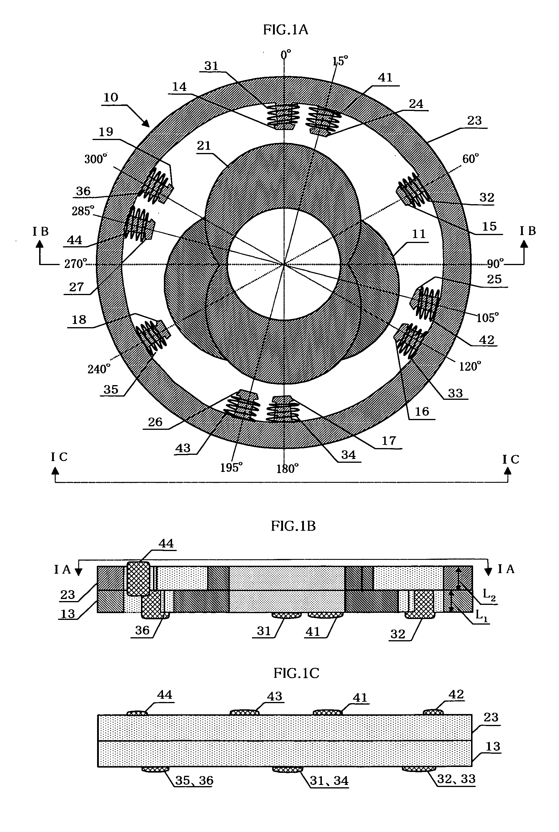
[0046]FIGS. 1A to 1C are views showing the configuration of a high-accuracy, 1X VR resolver according to the present invention, wherein FIG. 1A is a cross section of the resolver taken along a line IA—IA of FIG. 1B, FIG. 1B is a cross section of the resolver taken along a line IB—IB of FIG. 1A, and FIG. 1C is a side view of the resolver as viewed from a line IC—IC of FIG. 1A.

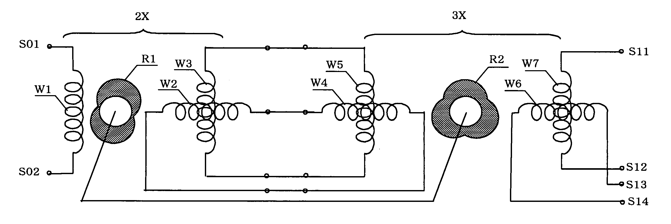
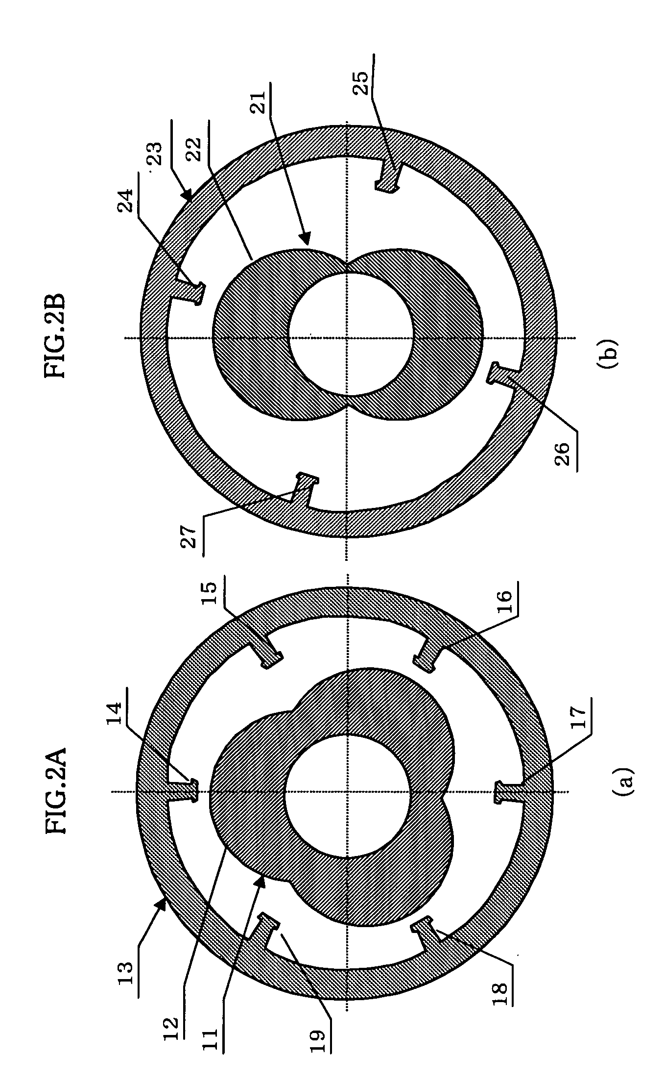
[0047]FIGS. 2A and 2B are sectional views showing the structures of a 2X resolver unit and a 3X resolver unit of the high-accuracy, 1X VR resolver.

[0048]A first embodiment to be described below exemplifies the case where N is 3; i.e., the shaft angle multiplier of NX is a shaft angle multiplier of 3X, and the shaft angle multiplier of (N−1)X is a shaft angle multiplier of 2×.

[0049]As shown in FIGS. 2A and 2B, a VR resolver 10 of the first embodiment consists of first and second resolver units superposed together. The first resolver unit includes a first rotor portion 11, and a first stator portion 13 surrounding...

example 1

[0064]Magnetic poles of the 3X stator portion: 6 poles at intervals of 60° (identical with those in the first embodiment)[0065]Magnetic poles of the 2X stator portion: 45°, 135°, 225°, 315°[0066]Salient poles of the 3X rotor portion: the center of the first salient pole is located at 0°.[0067]Salient poles of the 2X rotor portion: the center of the first salient pole is located at 45°.

example 2

[0068]Magnetic poles of the 3X stator portion: 6 poles at intervals of 60°(identical with those in the first embodiment)[0069]Magnetic poles of the 2X stator portion: 75°, 165°, 255°, 345°[0070]Salient poles of the 3X rotor portion: the center of the first salient pole is located at 0°.[0071]Salient poles of the 2X rotor portion: the center of the first salient pole is located at 75°.


PUM


Abstract

A high-accuracy, 1X VR resolver includes a first rotor portion having (N−1) salient poles, where N is an arbitrary integer not less than 3, a second rotor portion having N salient poles, a first stator portion having an input coil and an output coil for a shaft angle multiplier of (N−1)X are provided, and a second stator portion having an input coil and an output coil for a shaft angle multiplier of NX. A first resolver unit composed of the first rotor portion and the first stator portion, and a second resolver unit composed of the second rotor portion and the second stator portion are disposed in front and rear stages, respectively. The output coil of the stator portion in the front stage is connected to the input coil of the stator portion in the rear stage in such a manner that the output coil of the stator portion in the rear stage outputs an output signal for a shaft angle multiplier of 1X.

Description

BACKGROUND OF THE INVENTION[0001]1. Field of the Invention[0002]The present invention relates to a high-accuracy, variable-reluctance (VR) resolver whose shaft angle multiplier is 1X and which is used for, for example, measurement or control of a rotational angle or position.[0003]2. Description of the Related Art[0004]A variable-reluctance (VR) resolver, which includes a stator having an excitation coil and output coils wound around its magnetic poles, and a rotor having an arbitrary salient pole shape, outputs a resolver signal, which is a two-phase voltage signal including a sin voltage signal and a cos voltage signal, which vary with a rotational angle of the rotor. Such a VR resolver must output a resolver signal whose shaft angle multiplier is 1X (hereinafter referred to as “1X resolver signal”) and which serves as a reference for detection of an absolute position.[0005]A VR resolver whose shaft angle multiplier is 1X (hereinafter referred to as “1X VR resolver”) is formed fro...

Claims


Application Information

Patent Timeline
Patent Type & Authority Patents(United States)
IPC IPC(8): G01D5/244G01D5/245G01D5/12G01D5/20H02K16/00H02K24/00
CPCG01D5/2046
Inventor MATSUURA, MUTSUMIMIYA, TAIICHIOSANAI, YOSHIHITO
Owner MINEBEA CO LTD
Why Eureka
Try Eureka