Microrheology methods and systems using low-coherence dynamic light scattering

a microrheology and dynamic light scattering technology, applied in the direction of direct flow property measurement, instruments, measurement devices, etc., can solve the problems of large-scale rheological instruments used for soft materials, incomplete prior art systems with various deficiencies, and general limitations in frequency ranges of prior art systems at several khz, etc., to achieve high degree of experimental flexibility and applicability

Active Publication Date: 2005-10-25
CENT FLORIDA UNIV OF +2
View PDF11 Cites 41 Cited by
  • Summary
  • Abstract
  • Description
  • Claims
  • Application Information

AI Technical Summary

Benefits of technology

[0015]The fourth object of the invention is to provide microrheology methods and systems that use fiber optics for in-situ analysis that offers high degrees of experimental flexibility and applicability. For example, the novel invention can also be used for on-line sensing in industrial environment applications.
[0016]The fifth object of the invention is to provide microrheology methods and systems that allows for properties under investigation to be able to be probed locally to reveal detailed information about its morphology.

Problems solved by technology

However, there are problems with using rheological instrumentation for soft type materials.
However, the entire prior art systems have various deficiencies.
The frequency ranges of these prior art systems are generally limited at several kHz.
To the inventors' knowledge, there are no applicable real in-situ methods systems available to overcome the problems described above.

Method used


Image

  • Microrheology methods and systems using low-coherence dynamic light scattering
  • Microrheology methods and systems using low-coherence dynamic light scattering
  • Microrheology methods and systems using low-coherence dynamic light scattering

Examples


first preferred embodiment

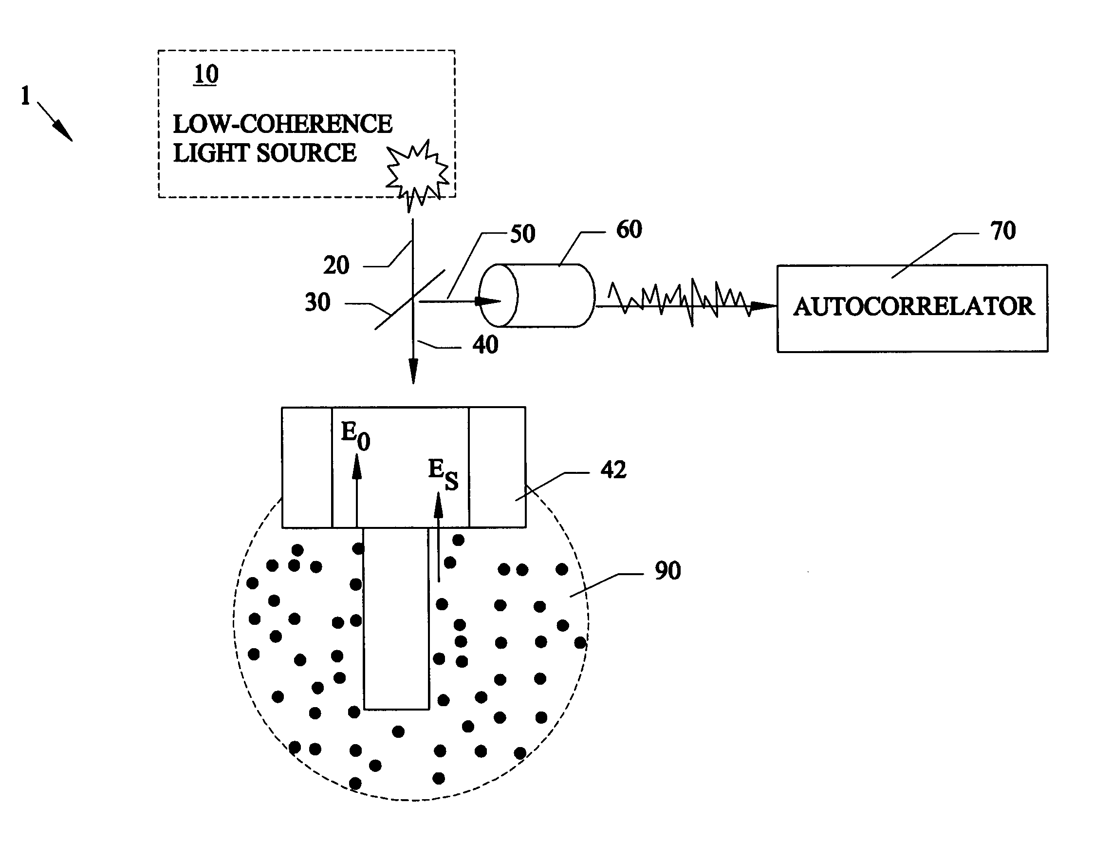
[0046]FIG. 6 further describes a first preferred embodiment 100 of a low-coherence radiation being emitted by a low-coherence light source 10 such as a superluminescent diode which can be coupled into a single-mode optical fiber 20, which represents one arm a 1×2 fiber coupler 20, 30, 40, 50. The output 42 of the coupler can be immersed in the fluid 90 under investigation. The light backscattered by the probe particles can be collected through the same fiber 40 through fiber 50 to the detector 60 and the signal can be analyzed in the frequency domain by a spectrum analyzer 80 such as SR760.

[0047]The signal detected is an interference of two electromagnetic fields: the fluctuating field backscattered by the particles undergoing thermal motion and the static field due to Fresnel reflection at the fiber-fluid interface. The fluctuating light can be detected only from the coherence volume, defined by the coherence length and the transversal dimension of the fiber core, in which the opti...

second preferred embodiment

[0065]FIG. 8 shows a second preferred embodiment 200 of the microheology low-coherence light scattering invention used with a medium to be tested using a time correlator 210. The other components in FIG. 8 are identical to and function similar to that of the previous figures.

[0066]Referring to FIG. 8, the analysis of the dynamic signal originating in the picoliter volume 90 can be performed in the time domain. Instead of a frequency analyzer one could use a temporal correlator 210 (for instance Brookhaeven 2-000) to obtain the temporal autocorrelation function of the fluctuating signal. It is known that between time and frequency domains there is a strict relationship determined by a conventional Fourier transformation. The entire analysis described before can be performed in the time domain using data provided by a time correlator.

third preferred embodiment

[0067]FIG. 9 shows a third preferred embodiment 300 of the microheology low-coherence light scattering invention using a fiber splitter 310 and reference mirror 320.

[0068]Referring to FIG. 9, the reference field can be provided by another fiber 325 as shown in the figure. In this case, the reflection from the end of the fiber in contact with the medium is suppressed by, for instance, angle cut. A two-by-two fiber optic splitter 310 can be used to provide the necessary reference filed. Reflection from the end of the fourth fiber 325 or from an external mirror 320 at this end can provide the reference field. This embodiment eliminates the reflectivity requirement in the measurement fiber. The rest of the operation is functionally identical with the previous embodiments.


PUM

PropertyMeasurementUnit
frequencyaaaaaaaaaa
volumesaaaaaaaaaa
diameteraaaaaaaaaa

Abstract

Methods and systems for using dynamic light scattering, for investigating local rheological responses of complex fluids over a frequency range larger than that provided by standard instrumentation. A low-coherence radiation source is used with fiber optics to allow measurements of small volume spacing of up to approximately 1/10 of a picoliter. The methods and systems are based on dynamic light scattering, for investigating the local rheological response of a complex fluid over a frequency range larger than that provided by standard mechanical instrumentation. The low-coherence radiation used in a fiber optics configuration allows the measurements to be confined to a small volume around a tenth of a picoliter. The ability of the method to accurately measure both loss and storage moduli has been tested using both simple Newtonian liquids and viscoelastic, complex fluids. Monitoring liquid-gel transitions in polymer solutions has also been demonstrated. The unique capability of the technique to localize the measurement volume can be used for three-dimensional mapping of rheological properties in heterogeneous systems. Other embodiments can use open-air setups instead of optical fibers to transmit and receive the low coherence light.

Description

[0001]This invention relates to dynamic light scattering, and in particular to methods and systems for using low-coherence light sources with an optical fiber probe to investigate rheological effects such as loss and storage moduli parameters liquids, and this invention claims the benefit of U.S. Provisional application 60 / 327,226 filed Oct. 5, 2001.BACKGROUND AND PRIOR ART[0002]Through present date, a broad range of rheological instrumentation exists for applications in food products, paints and coatings, polymers and composites, asphalt, pharmaceuticals, electronic materials, etc. For specific purposes, special viscometers such as an oscillating capillary viscometer, automated rolling ball viscometer and a high shear capillary viscometer are now being used. However, there are problems with using rheological instrumentation for soft type materials.[0003]Soft materials, which include polymer solutions, surfactant solutions, and biological materials, among others, are characterized b...

Claims


Application Information

Patent Timeline
Patent Type & Authority Patents(United States)
IPC IPC(8): G01B9/02G01N11/02G01N21/49
CPCG01N11/02G01N21/49G01N2011/008
Inventor DOGARIU, ARISTIDEPOPESCU, GABRIELRAJAGOPALAN, RAJ
Owner CENT FLORIDA UNIV OF
Why Eureka
Try Eureka