Apparatus and method having an optical fiber disposed circumferentially around the pipe for measuring unsteady pressure within a pipe

Inactive Publication Date: 2005-11-01
EXPRO METERS
View PDF5 Cites 93 Cited by
  • Summary
  • Abstract
  • Description
  • Claims
  • Application Information

AI Technical Summary

Benefits of technology

[0007]The present invention provides a significant improvement over the prior art by providing a non-intrusive pressure sensor for the measurement of unsteady pressure in a pipe using fiber optic sensing. Also, the present invention eliminates the need for electronic components down-hole, thereby improving reliability of the measurement. Still further, the present invention is inherently safe and explosion proof as compared to electrical systems. The present invention may also provide circumferentially averaged pressure and/or axially aver

Problems solved by technology

Drilling holes in the pipe can be cost

Method used


Image

  • Apparatus and method having an optical fiber disposed circumferentially around the pipe for measuring unsteady pressure within a pipe
  • Apparatus and method having an optical fiber disposed circumferentially around the pipe for measuring unsteady pressure within a pipe
  • Apparatus and method having an optical fiber disposed circumferentially around the pipe for measuring unsteady pressure within a pipe

Examples


Embodiment Construction

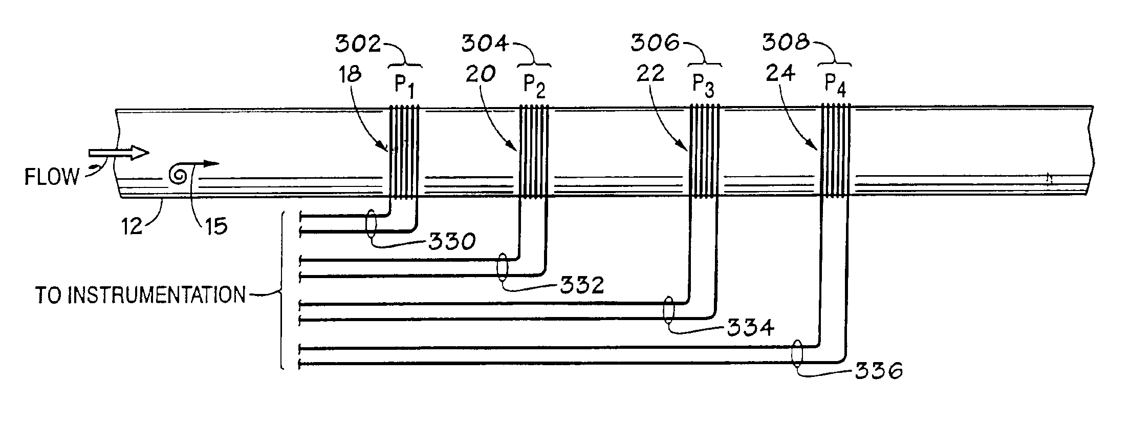
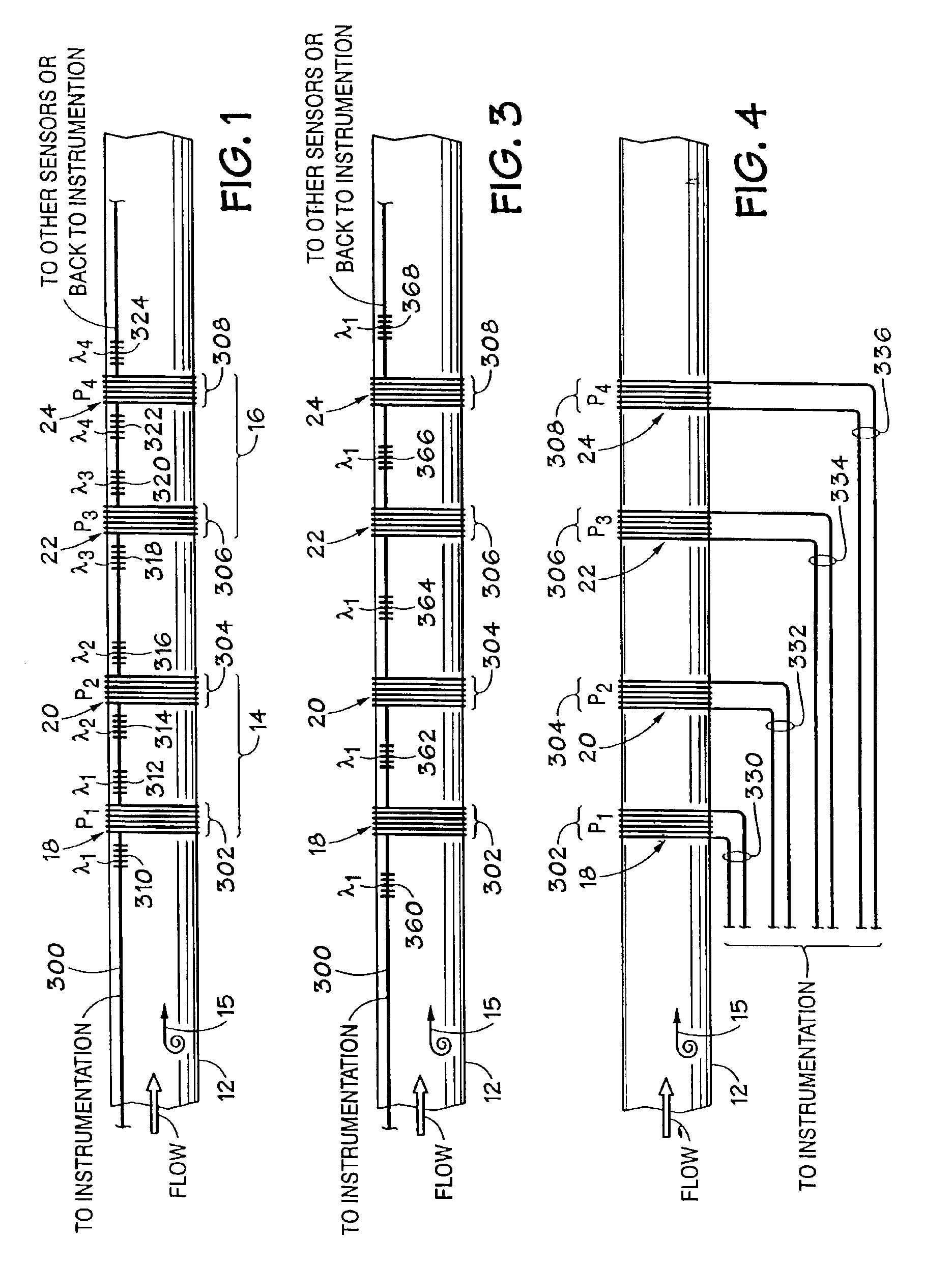
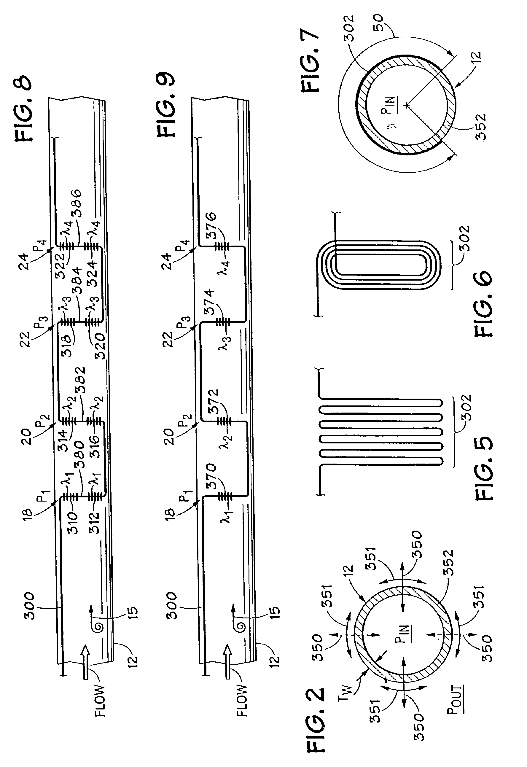
[0018]Referring to FIG. 1, a pipe (or conduit) 12 is provided with a plurality of non-intrusive, distributed fiber grating based pressure sensors 18-24 located along the pipe 12. Each of the pressure sensors 18-24 comprises corresponding coils 302-308 having a predetermined length wrapped around the pipe 12. Each of the sensors 14-18 comprises one or more Bragg gratings 310-324 having predetermined reflection wavelengths λ1, λ2, λ3, and λ4 associated therewith.

[0019]The gratings 310-324 are similar to that described in U.S. Pat. No. 4,725,110, entitled “Method for Impressing Gratings Within Fiber Optics”, to Glenn et al; however, any wavelength tunable grating or reflective element embedded in the fiber 10 may be used if desired. A Bragg grating, as is known, reflects a predetermined wavelength band of light having a central peak reflection wavelength λb, and passes the remaining wavelengths of the incident light (within a predetermined wavelength range). Accordingly, input light 40...


PUM


Abstract

A fiber optic pressure sensor for measuring unsteady pressures within a pipe include at least one optical fiber disposed circumferentially around a portion of a circumference of the pipe, which provides an optical signal indicative of the length of the optical fiber. An optical instrument measures the change in length of the optical fiber to determine the unsteady pressure within the pipe. The pressure sensor may include a plurality of optical fiber sections disposed circumferentially around a portion of the circumference of the pipe that are optically connected together by optical fiber sections disposed axially along the pipe. The optical fiber sections may include fiber Bragg gratings having substantially the same or different reflection wavelengths to permit for example the sensors to be axially distributed along the fiber using wavelength division multiplexing and/or time division multiplexing.

Description

CROSS REFERENCE TO RELATED APPLICATIONS[0001]This application is a continuation of commonly owned co-pending U.S. patent application Ser. No. 09 / 344,093, entitled “Non-Intrusive Fiber Optic Pressure Sensor for Measuring Unsteady Pressures within a Pipe” filed Jun. 25, 1999 now U.S. Pat. No. 6,450,037 which is a continuation-in-part of commonly owned U.S. patent application, Ser. No., 09 / 105,525, entitled “Non-Intrusive Fiber Optic Pressure Sensor for Measuring Pressure Inside, Outside and Across Pipes”, filed Jun. 26, 1998 now abandoned.TECHNICAL FIELD[0002]This invention relates to sensing pressure around pipes and more particularly to a non-intrusive fiber optic pressure sensor for measuring unsteady pressures within a pipe.BACKGROUND ART[0003]It is known in the oil and gas industry that the measurement of fluid pressure in a down-hole pipe is useful to the exploration and production of oil and gas. However, typical pressure sensors require that a hole be drilled in the pipe to po...

Claims


Application Information

Patent Timeline
IPC IPC(8): G01L11/00G01L11/02G01L1/24G01L1/00E21B47/06
CPCE21B47/06G01L1/246G01L11/025
Inventor BRYANT, REBECCA S.GYSLING, DANIEL L.WINSTON, CHARLES R.DAVIS, ALLEN R.FAUSTINO, JOHN M.
Owner EXPRO METERS
Why Eureka
Try Eureka