Crankshaft for an internal combustion engine

a crankshaft and internal combustion engine technology, applied in the direction of shafts, pivots, shafts, etc., can solve the problems of difficult to share the crankshaft among a plurality of engine types, noisy operation of gears, and significant variations in load on each tooth, so as to achieve greater flexibility in use

Inactive Publication Date: 2005-11-01
HONDA MOTOR CO LTD
View PDF2 Cites 16 Cited by
  • Summary
  • Abstract
  • Description
  • Claims
  • Application Information

AI Technical Summary

Benefits of technology

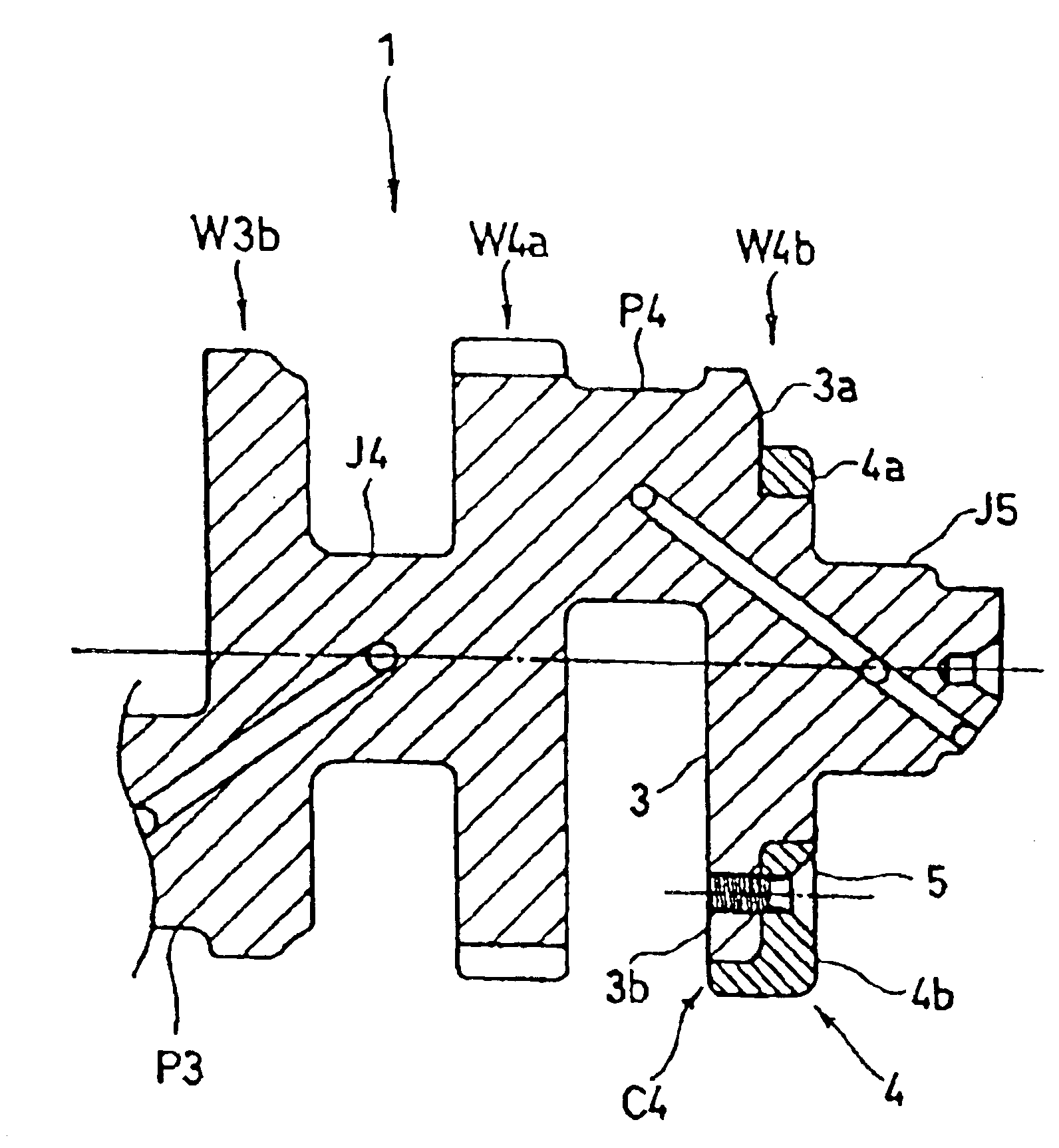
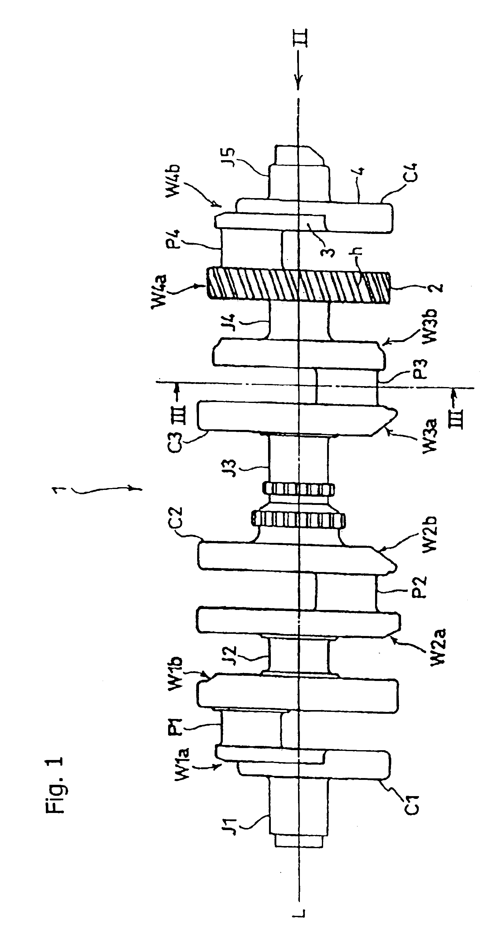
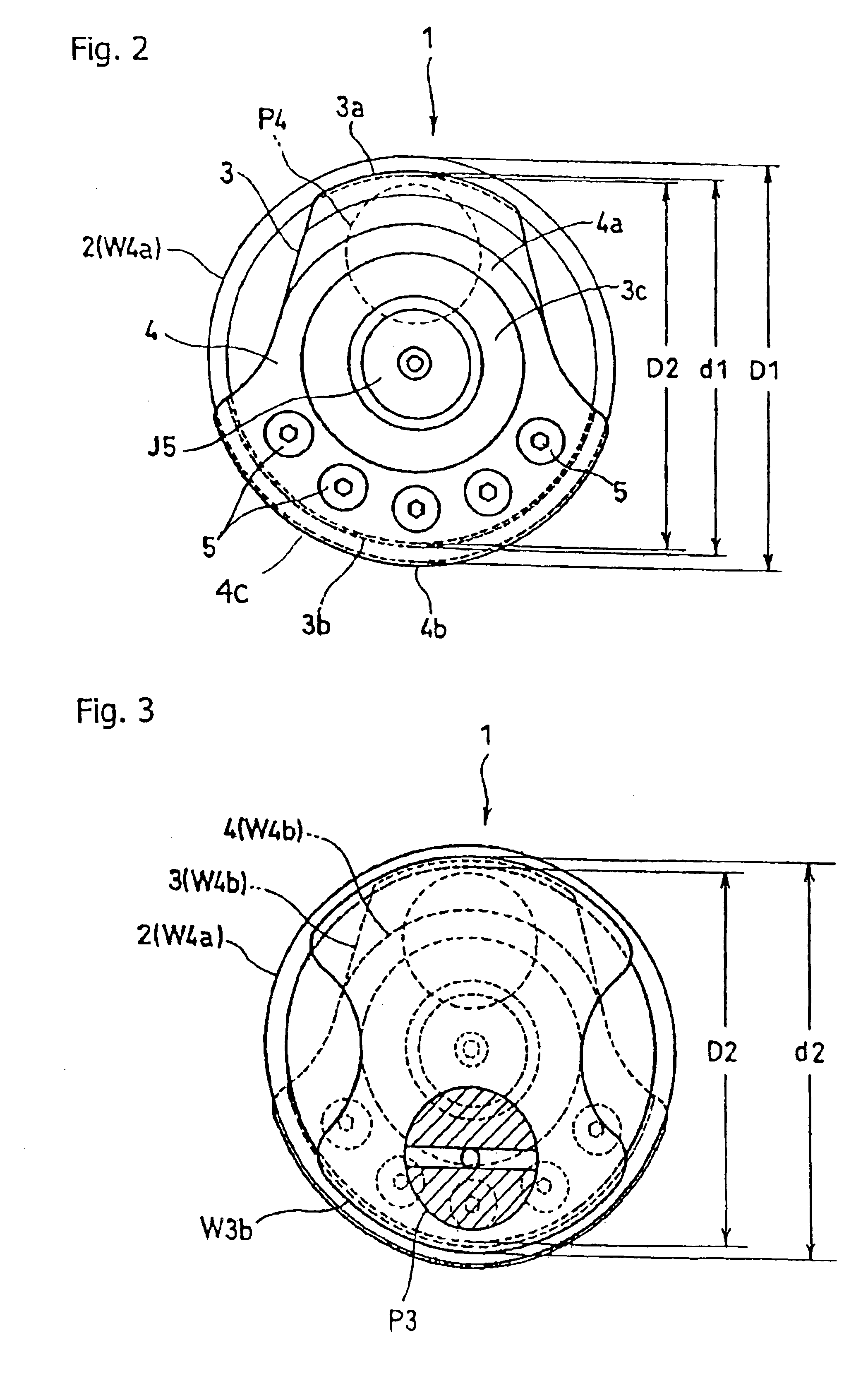
[0013]The present invention provides an improved crankshaft for an internal combustion engine, in which a primary drive gear, which is a helical gear, is provided by a modified crank web of the crankshaft. The crankshaft hereof also includes a split crank web, which is connected to the primary drive gear via a crankpin. Optionally, the crankshaft may include a second split crank web at an end opposite the first split crank web, to allow for greater flexibility in use.
[0014]The helical gear provided on the crank web of the crankshaft is high in intermeshing rate, and experiences less variation in load exerted on each tooth than a spur gear, whereby mechanical noise may be reduced, and smooth power transmission can be achieved.
[0015]When the gear provided on the crank web is a helical gear, grinding of helical teeth may be skewed by the helix angle of a tooth trace, and as a result, the crank webs on both sides of the gear need not be made smaller than the bottom diameter of the helical gear.
[0021]In this manner, since the first balance weight mounting portion is provided on the outside of the crankpin located at one end out of the plurality of crankpins and the second balance weight mounting portion is provided on the outside of the crankpin located at the other end, the first balance weight mounting portion and the second balance weight mounting portion are well balanced in terms of position, and thus when changing the first balance weight and the second balance weight, they can be set relatively easily.
[0023]In this manner, although meshing noise of the gear can be reduced, and hence quietness may be improved by employing the helical gear as the main drive gear, since it is necessary to incline the machining tool with respect to the gear for machining the helical gear, and hence probability of interference with the crank web which is located on the opposite side of the crankpin from the gear increases, the structure in which the crank web is divided into the first balance weight mounting portion and the first balance weight, as described above, is further effective.

Problems solved by technology

In the known crankshaft described above, although one of the crank webs is configured as a spur gear, variations of load exerted on each tooth are significant, and operation of the gear may be noisy.
Moreover, since it is generally necessary to match an inertia moment of the crankshaft to respective engines having different properties, in the known crankshaft including the structure described above, it is difficult to share the crankshaft among a plurality of engine types.

Method used


Image

  • Crankshaft for an internal combustion engine
  • Crankshaft for an internal combustion engine
  • Crankshaft for an internal combustion engine

Examples


second embodiment

[0068]A second embodiment of a crankshaft 12 according to the present invention is depicted in FIGS. 6-9.

[0069]The engine 11 depicted in FIG. 6 includes a crankshaft 12, a crankcase 15 rotatably supporting crank journals 13a-13e located at a plurality of or, more specifically, five positions of the crankshaft 12 by crank journal bearings 14a-14e located at a plurality of or, more specifically, five positions. The engine 11 illustrated in FIG. 6 also includes four pistons 19a-19d connected to crankpins 17a-17d at four positions on the crankshaft 12 via four connecting rods 18a-18d, respectively. The engine 11 further includes a cylinder block 21 mounted on the upper side of the crankcase 15, for guiding sliding motion of the respective pistons 19 on the inner surfaces 20a to 20d of respective cylinders, and a cylinder head 22 mounted on the upper side of the cylinder block 21 for holding a valve mechanism (not shown).

[0070]The engine 11 is provided with an associated transmission 25,...


PUM


Abstract

A crankshaft has a helical drive gear formed as one of the crank webs at an end portion thereof. Another crank web outside of the drive gear is made in two parts, an integral balance weight mounting portion and a removable balance weight. In one embodiment, a crankshaft 12 features a crankshaft body 33 including a gear 24 for outputting rotation formed on one side of a crankpin 17d. The crankshaft also includes a first balance weight mounting portion 30g formed on the other side of the crankpin 17d and a first balance weight 31g to be mounted to the first balance weight mounting portion 30g. The crankshaft body 33 may be formed with a second balance weight mounting portion 30a separately from the first balance weight mounting portion 30g, and a second balance weight 31a mounted to the second balance weight mounting portion.

Description

CROSS-REFERENCE TO RELATED APPLICATIONS[0001]The present application claims priority under 35 USC 119 based on Japanese patent application No. 2003-074457, filed Mar. 6, 2003, and also claims priority based on Japanese patent application No. 2003-059769, filed Mar. 18, 2003.BACKGROUND OF THE INVENTION[0002]1. Field of the Invention[0003]The present invention relates to a crankshaft for an internal combustion engine. More particularly, the present invention relates to a crankshaft including a crank web configured as a helical drive gear, and also including a two-piece crank web including a removable annular weight.[0004]2. Description of the Background Art[0005]Many different designs for internal combustion engines are known, and many different engines are commercially available. In a motorcycle engine, for example, a piston is reciprocated by heat energy obtained by burning an air-fuel mixture. Reciprocal motion of the piston is converted, via a connecting rod, to rotary motion of t...

Claims


Application Information

Patent Timeline
Patent Type & Authority Patents(United States)
IPC IPC(8): F16C3/08F16C3/04F16F15/26
CPCF16F15/26F16C3/08Y10T74/2183Y10T74/2174
Inventor GOKAN, YOSHITSUGA
Owner HONDA MOTOR CO LTD
Why Eureka
Try Eureka