
Black layer coated heat exchanger

a heat exchanger and black layer technology, applied in indirect heat exchangers, air heaters, lighting and heating apparatus, etc., can solve the problems of low emissivity low heat dissipation efficiency of aluminized steel, and high cost of aluminized steel heat exchangers, so as to increase the emissivity of heat exchangers and emit more hea

Inactive Publication Date: 2005-11-01
CARRIER CORP
View PDF8 Cites 2 Cited by
  • Summary
  • Abstract
  • Description
  • Claims
  • Application Information

AI Technical Summary

Benefits of technology

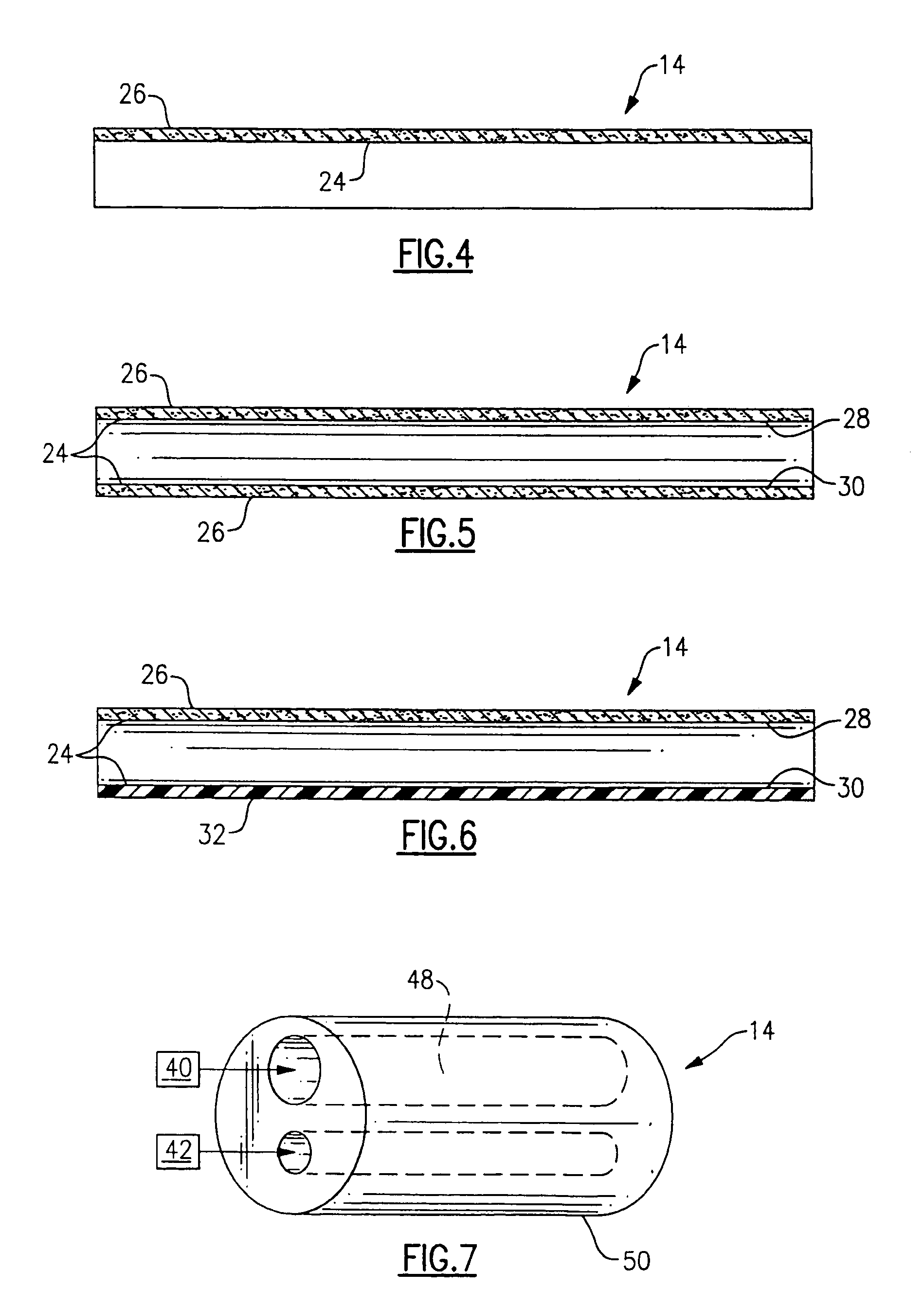
[0007]The present invention relates to a furnace heat exchanger for use with a primary heat exchanger of a condensing furnace or a single heat exchanger of a mid-efficiency furnace which includes a layer of oxidized black coating which increases the emissivity of the heat exchanger and allows the heat exchanger to emit more heat.
[0010]As the cupric oxide layer is black, the layer has a high emissivity and emits more heat, increasing the efficiency of the heat exchanger. Also, as cupric oxide has a high decomposition temperature, the cupric oxide is not affected by the flame of the burner which may contact part of the heat exchanger. It is preferable that cupric oxide be coated on both sides of the heat exchanger to further increase efficiency.
[0011]Alternatively, the furnace heat exchanger is formed of a steel alloy and is controllably oxidized to form a black coating of magnetite (Fe3O4) which increase the emissivity of the heat exchanger.
[0012]Accordingly, the present invention provides a furnace heat exchanger which includes a layer of oxidized black coating which increases the emissivity of the heat exchanger and allows the heat exchanger to emit more heat.

Problems solved by technology

As the aluminized steel is shiny, the steel does not radiate heat well and has a low emissivity.
There are several drawbacks to the aluminized steel heat exchanger of the prior art.
For one, aluminized steel is expensive.
Additionally, as the aluminized steel has a low emissivity, the steel does not radiate heat well.

Method used


Image

  • Black layer coated heat exchanger
  • Black layer coated heat exchanger
  • Black layer coated heat exchanger

Examples


Embodiment Construction

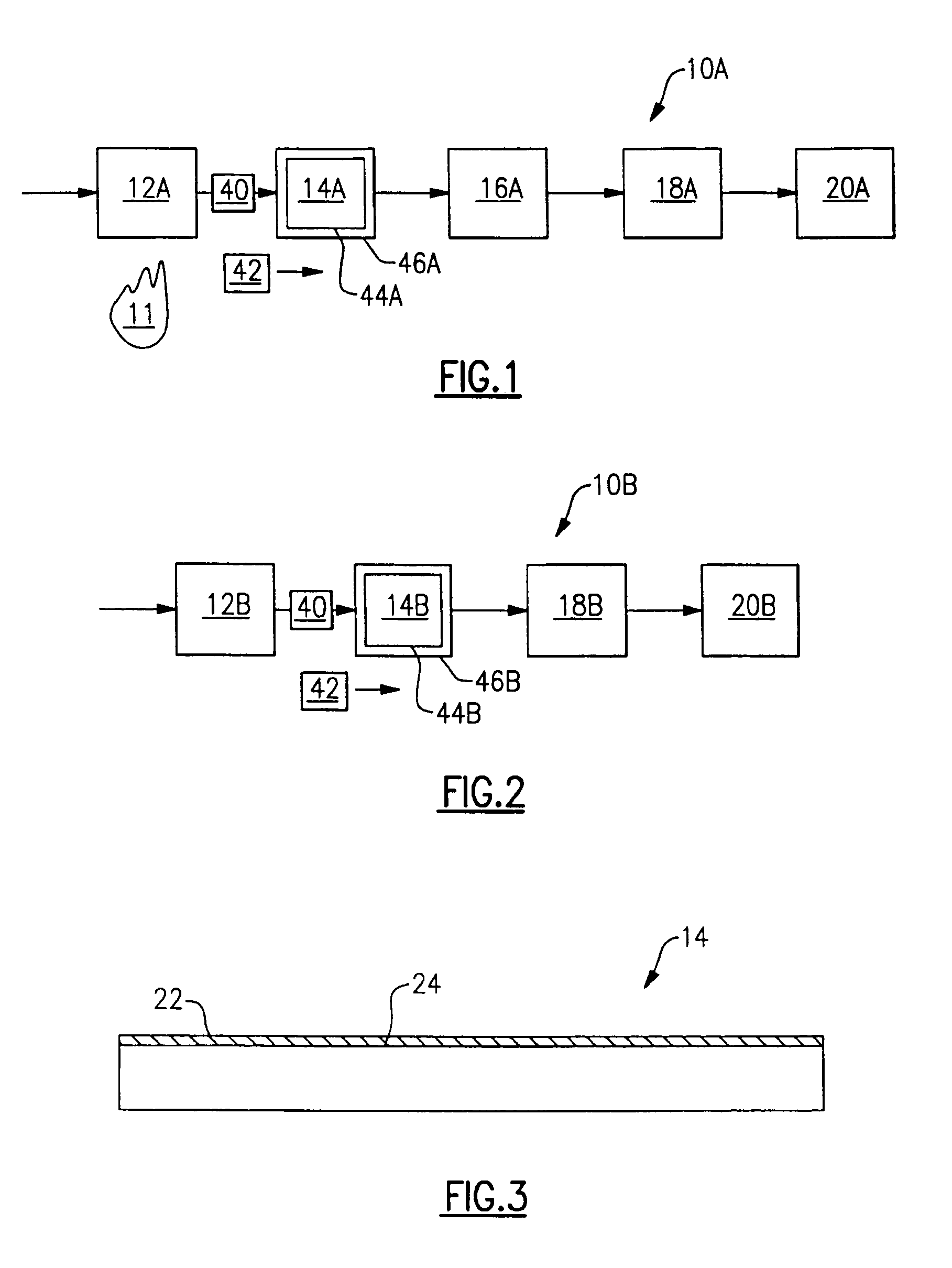
[0022]FIG. 1 schematically illustrates a condensing furnace system 10A. Air and natural gas enter a burner 12A which burns the air and natural gas by a flame 11 to produce hot combustion products 40. The hot combustion products 40 pass through a primary heat exchanger 14A, which cools the hot combustion products 40 and extracts heat to the air 42 to be heated. The air 42 to be heated and the hot combustion products 40 exchange heat in the primary heat exchanger 14A. The air 42 in the primary heat exchanger 14 accepts heat from the hot combustion products 40, heating the air 42. The hot combustion products 40 flow on one side 44A of the primary heat exchanger 14A, and the air 42 flows on an opposing side 46A of the primary heat exchanger 14. For example, as illustrated in FIG. 1, the hot combustion products 40 flow inside the primary heat exchanger 14A and the air 42 flows outside the primary heat exchanger 14A. However, it is to be understood that the hot combustion products 40 can ...


PUM

PropertyMeasurementUnit
Emissivityaaaaaaaaaa
Combustionaaaaaaaaaa

Abstract

Hot combustion products exchange heat with air in a heat exchanger of a condensing furnace. The hot combustion products flow on one side of the heat exchanger, and the air flows on the opposing side of the heat exchanger. The heat exchanger is electrochemically coated with a coating of copper metal. The copper coating is oxidized with an aqueous oxidizing alkaline solution to form a matte black layer of cupric oxide. As the layer of cupric oxide is black, the layer has a high emissivity and emits more heat, increasing the efficiency of the primary heat exchanger. Alternatively, iron can be electrochemically coated on the primary heat exchanger and oxidized to black magnetite to increase emissivity.

Description

[0001]This application is a continuation in part of patent application Ser. No. 09 / 927,274 filed on Aug. 10, 2001.BACKGROUND OF THE INVENTION[0002]The present invention relates generally to a heat exchanger for use with the primary heat exchanger of a condensing furnace or the single heat exchanger of a mid-efficiency furnace which includes a layer of oxidized black coating which increases the emissivity of the heat exchanger and allows the heat exchanger to emit more heat.[0003]A condensing furnace generally includes two heat exchangers, a primary heat exchanger and a condensing heat exchanger. Air and natural gas enter a burner where they are burned to form hot combustion products. The primary heat exchanger cools the hot combustion products, extracting and supplying heat to the air that is to be heated. A standard (“mid-efficiency”) furnace generally includes only a single heat exchanger which cools the hot combustion products, extracting and supplying heat to the air to be heate...

Claims


Application Information

Patent Timeline
IPC IPC(8): C25D7/00F28F13/18F28F13/00F24H8/00
CPCC25D7/00F28F13/182F24H8/00Y10T29/4935Y02B30/102Y10S165/904F28F2245/06Y02B30/00
Inventor OTTER, JAMES W.
Owner CARRIER CORP
Learn More