Non-fragmenting pressure relief apparatus

a pressure relief apparatus and forward-acting technology, applied in mechanical equipment, transportation and packaging, valve types, etc., can solve problems such as failure to protect devices, dangerous pressure build-ups in enclosures, piping or containment vessels, etc., and achieve the effect of reducing the risk of explosion

Inactive Publication Date: 2005-11-01
FIKE CORP
View PDF21 Cites 22 Cited by
  • Summary
  • Abstract
  • Description
  • Claims
  • Application Information

AI Technical Summary

Benefits of technology

[0012]Non-fragmenting, forward-acting pressure relief apparatus in accordance with this invention includes either a single rupture disc, or a pair of rupture discs, each having a central section and a peripheral flange section. The apparatus is adapted to be mounted on structure defining a vent opening communicating with structure or equipment to be protected from overpressure events.
[0014]Upon application of a force to the central section of the disc or discs sufficient to effect rupture of the line of weakness of each, the central section or sections of the discs defined by the line of weakness opens to vent the area of the equipment or structure protected by the pressure relief apparatus. Severing of the hinge area of the central section of each disc is precluded by virtue of the manner in which the forces on the end regions of the line of weakness which effect rupture thereof, are diverted away from the minimum width of the hinge area between the end regions of the line of weakness. In view of the fact that the end regions of each line of weakness are of semi-circular C-shaped configuration and therefore continuously converge toward one another and continuously diverge away from one another has the effect of diverting forces tending to severe the hinge area of each disc away from the minimum width of the hinge area upon opening of a respective rupture disc, thus preventing separation of the central sections of the discs from the flange portions of respective discs.
[0015]In another preferred embodiment of the vent apparatus, separate reinforcement panels are secured to one face of the central section of a disc (the concave face of the disc in the case of a disc having a bulged central section), with the C-shaped end regions of the line of weakness being provided in respective panels. In one version of this embodiment, the terminal ends of the main length of the line of weakness in the central section of the disc join with ends of opposed C-shaped, first converging and then diverging end region lines of weakness. In another version of this embodiment, two separate rupture discs are provided with the first overlying disc having only a main length of line of weakness without C-shaped end region lines of weakness. The second associated rupture disc has wing panels, which may be a part of a butterfly shaped member, secured to a surface of the disc remote from the first disc and is provided with opposed, C-shaped end region lines of weakness that extend from points that align with the terminal ends of the main line of weakness in the central section in the overlying first rupture disc. In view of the fact that the part of the underlying second disc having the panels secured thereto is of greater thickness than the remainder of the central section of that disc, additional reinforcement is provided for the hinge portion of the disc, which in conjunction with the curvilinear, outwardly diverging configuration of the end region lines of weakness, enhances prevention and tearing and severing of the hinge portion of the central section of the disc.
[0016]The lines of weakness in all embodiments of this invention are preferably defined by a series of end-to-end spaced slits through the thickness of the central section of each disc having unitary webs of the central section of a respective disc between adjacent ends of each of pair of slits. Upon application of a force against the central rupturable section of the discs of all embodiments of this invention sufficient to tear the unitary webs of disc material between adjacent ends of the slits defining the line of weakness, the rupturable sections of the discs open to vent the area protected by the pressure relief apparatus. Although the lines of weakness tear along the full length thereof upon rupture of the central section of the disc, including the outwardly diverging C-shaped end region lines of weakness, the hinge portions of the central sections of the discs are protected from tearing or severing because the forces effecting rupture of the webs between the individual end region line of weakness defining slits in the rupture discs tear in opposite directions away from the hinge portions of the rupture disc thus maintaining the integrity of the hinge portions of the central sections of the discs even though very high pressures are applied to the central sections of the disc upon occurrence of an overpressure or explosion, resulting in substantially instantaneous opening of the rupture discs.

Problems solved by technology

Many industrial processes involve handling and processing of materials that under certain conditions can create hazardous overpressures resulting from explosive conflagrations, or rapid rise in pressure from runaway processes, failure of protective devices such as pressure regulating valves, and similar unpredictable mishaps.
Exemplary in this respect are processes involving gases or dust particles in contained vessels or piping which can spontaneously ignite or produce an explosion from untoward events such as a spark or the like and that result in dangerous pressure build-ups within an enclosure, piping or containment vessels.
Bag houses or the like that are constantly at risk of explosions by virtue of the high concentration of dust within the bag house.
The same type of hazard must also be safely controlled in connection with processing equipment involving combustible gases or dust particles, pipes conveying gases or dust laden fluids from one part of a process to another or to a collection area, processing vessels in which a runaway reaction or untoward build-up of pressure in the vessel can occur without warning, and other industrial processes where an uncontrolled explosion or excessive build-up of pressure is a continuing safety hazard.
Notwithstanding the provision of anti-fragmentation hinge portions of the rupture discs structures of previous designs, the construction of such hinge areas has not been totally satisfactory to accommodate a multiplicity of overpressure events and conditions.
If the width of the hinge area is too great, the pressure value at which the rupturable section gives way is often times compromised resulting in failure of the rupture disc to open at a pre-selected value.
On the other hand, if the hinge area is narrowed in order to assure full opening of a rupture disc at a prescribed pressure value, the unitary hinge area tends to also rupture allowing the section of the disc which opens to tear away from the surrounding remaining flange portion of the disc and thereby produce a resultant dangerous metal projectile escaping from the rupture disc assembly at high velocity.

Method used


Image

  • Non-fragmenting pressure relief apparatus
  • Non-fragmenting pressure relief apparatus
  • Non-fragmenting pressure relief apparatus

Examples


Embodiment Construction

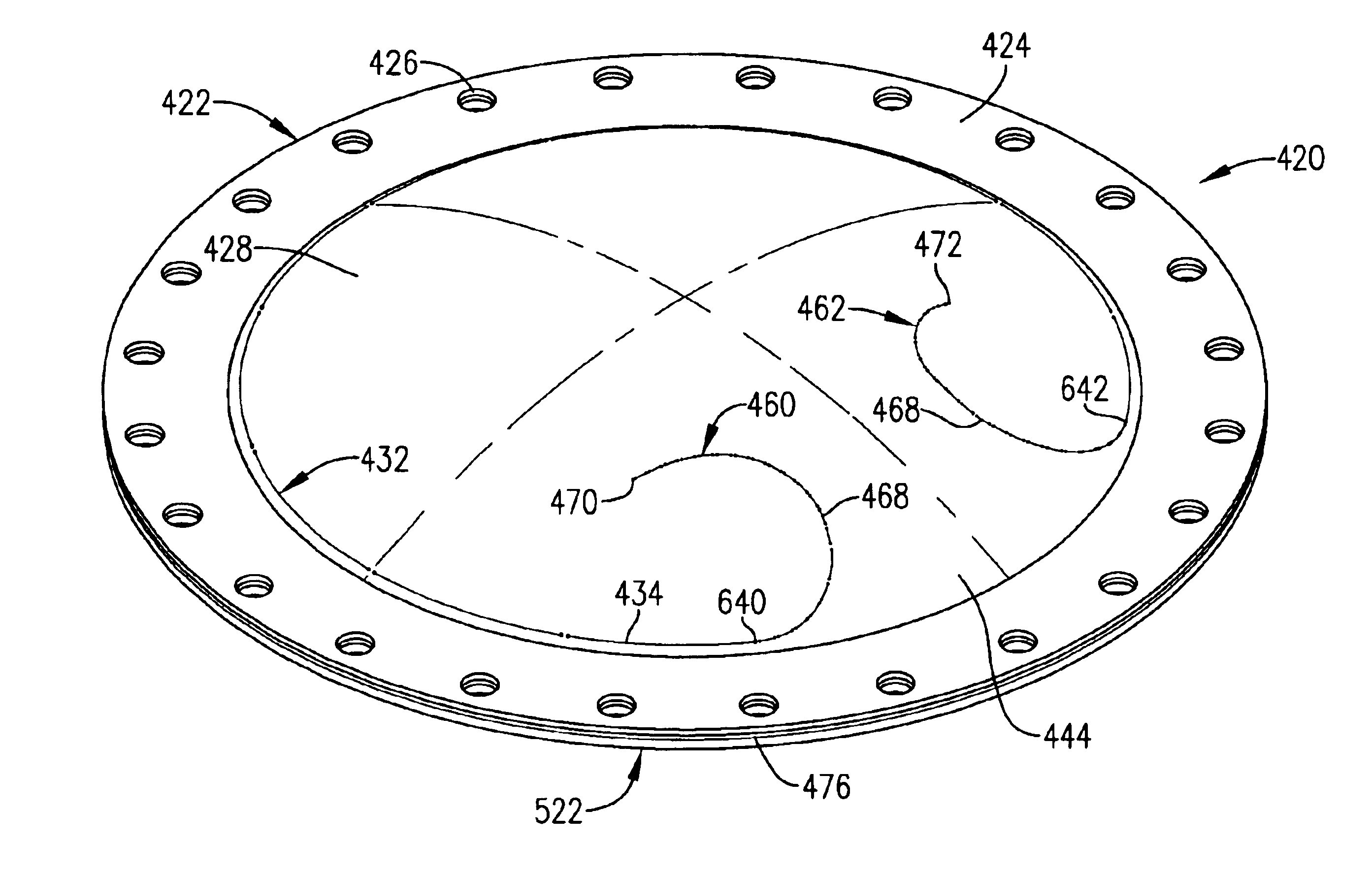
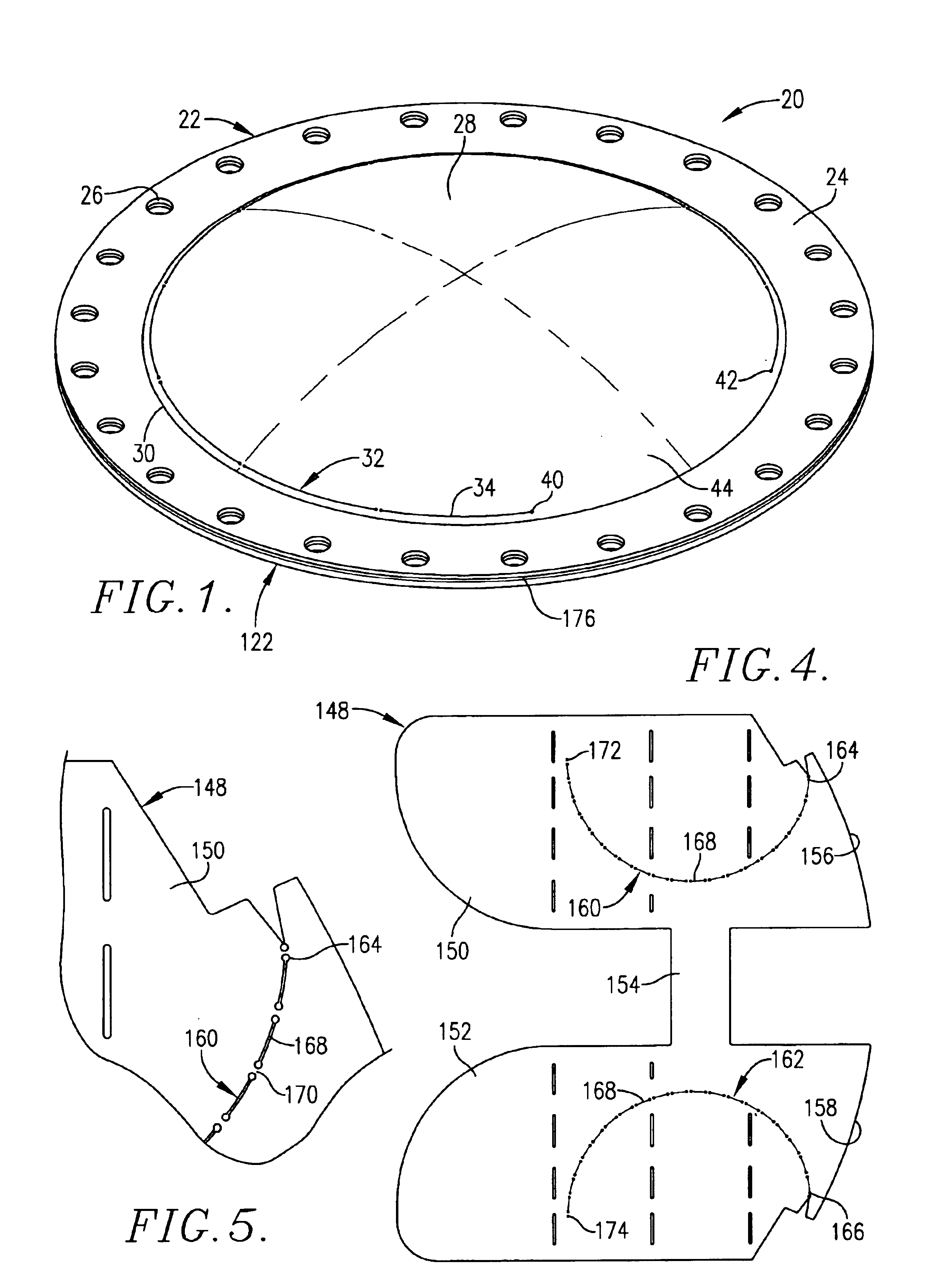
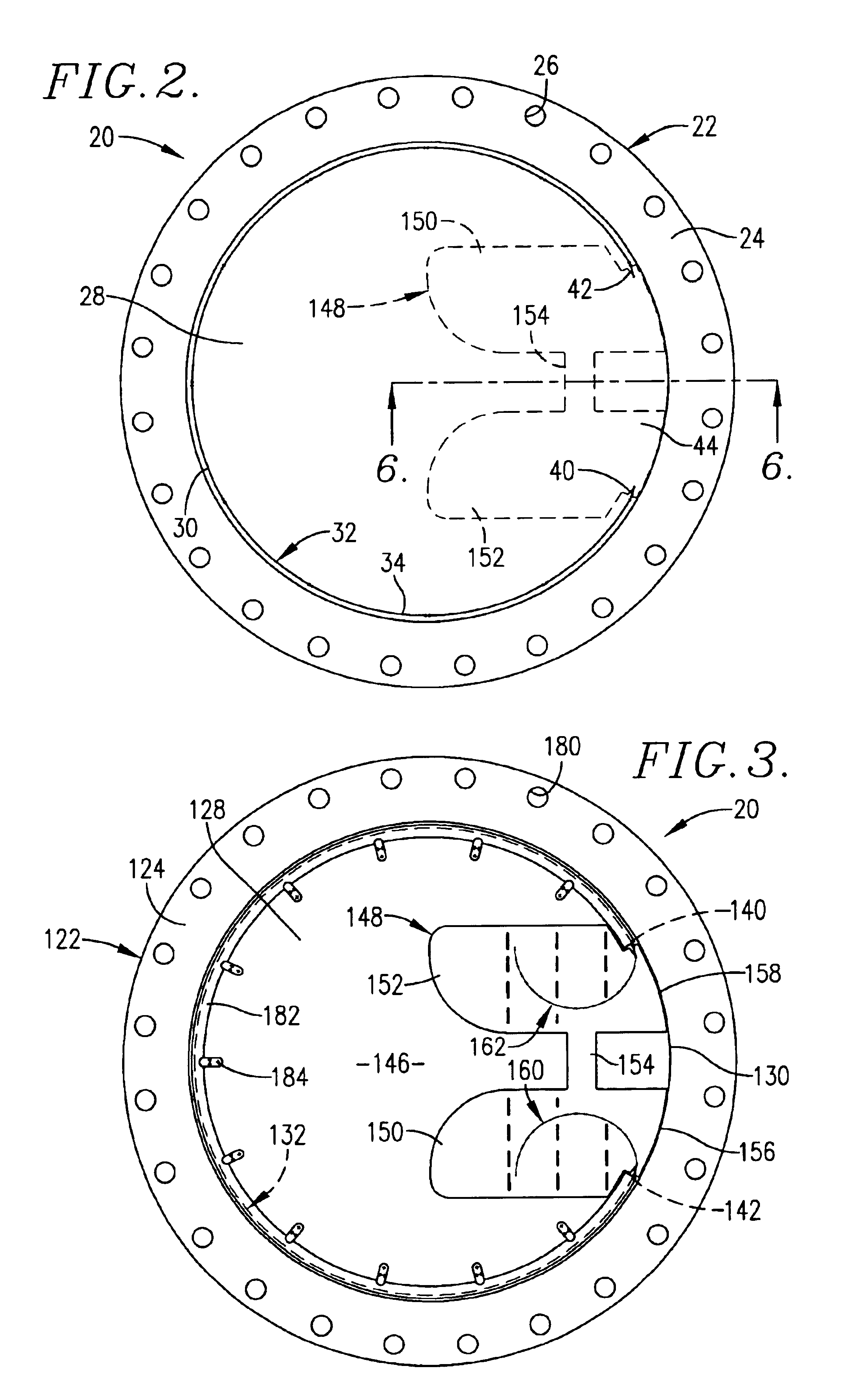
[0035]Non-fragmenting pressure relief apparatus in accordance with one preferred embodiment of this invention as shown in FIGS. 1-8 of the drawings, generally designated 20, is adapted to be mounted in overlying relationship to an opening leading to equipment or structure to be protected from a preselected overpressure condition. Apparatus 20 is especially useful for protecting processing equipment, pressure vessels, piping and structures including bag houses and the like from overpressures resulting from explosions and other potentially destructive and catastrophic high pressure occurrence. Although apparatus 20 is illustrated in the drawings as of circular configuration, the principals hereof are also applicable to rectangular or other polygonal non-fragmenting pressure relief apparatus.

[0036]Apparatus 20 includes a topmost or outermost rupture disc 22 normally constructed of a relatively thin corrosion resistant metal material such as stainless steel. Disc 22 in its circular embo...


PUM


Abstract

A non-fragmenting pressure relief apparatus includes a rupture disc having a central bulged or flat section and a peripheral flange portion. Certain embodiments of the invention have a butterfly shaped element having two wing panels attached to the underside of a rupture disc of the apparatus. A line of weakness of major length extends around the periphery of the central section of a disc and C-shaped end region lines of weakness in the wing panels, which define a hinge portion of the disc therebetween, first converge and then diverge from one another, and connect with the major line of weakness. Application of an overpressure to the rupture disc apparatus causes the entire line of weakness to sever including the end region lines of weakness whereby divergence of the opening force at the hinge portion of the disc prevents separation of the central section of the disc from the peripheral portion of the disc. In another embodiment, the butterfly shaped element is omitted and the C-shaped end region lines of weakness are provided in the central section of the disc.

Description

BACKGROUND OF THE INVENTION[0001]1. Field of the Invention[0002]This invention relates to non-fragmenting, forward-acting pressure relief apparatus used to protect processing equipment, pressure vessels, piping and structures from high pressure events and / or to vent such equipment when destructive and catastrophic overpressures result from any media where an explosion is a risk such as gas and dust particle explosions. Explosion hazards exist in connection with various types of gases and dust particles such as coal, flour, sugar, metal, and plastics. In particular, the invention concerns a single pressure relief rupture disc and composite rupture disc apparatus designed to rupture and vent a protected area, process or equipment whenever an overpressure condition occurs that exceeds a preselected value. The pressure relief rupture disc apparatus incorporates a rupture disc or rupture disc assembly which ruptures and vents an area when overpressure condition or explosion occurs wherei...

Claims


Application Information

Patent Timeline
Patent Type & Authority Patents(United States)
IPC IPC(8): B65D90/36B65D90/22F16K17/02F16K17/16
CPCB65D90/36F16K17/162Y10T137/1692Y10T137/1729B65D90/22F16K17/02F16K17/16
Inventor EIJKELENBERG, TOMDOM, GUIDO
Owner FIKE CORP
Why Eureka
Try Eureka