Cleaning sheet for probe needles

a technology for cleaning sheets and needles, applied in carpet cleaners, semiconductor/solid-state device testing/measurement, instruments, etc., can solve the problems of inability to use needles, inability to polish the tip sections of needles that need sufficient polishing to ensure contactability, and low polishing effect of each needle tip section. , to achieve the effect of greatly shortening the polishing processing time interval, automatic execution of effective needle tip polishing

Inactive Publication Date: 2005-11-01
LAPIS SEMICON CO LTD
View PDF11 Cites 27 Cited by
  • Summary
  • Abstract
  • Description
  • Claims
  • Application Information

AI Technical Summary

Benefits of technology

[0015]According to the invention, the surface-roughened first polishing layer for effectively polishing film-like foreign substances adhered to needle tip portions brought into contact with pads, and the second polishing layer made up of the elastic member containing the polishing grains for removing adherents attached to the entire needlepoints are provided in one cleaning sheet. Therefore, when, for example, needlepoint polishing is executed using an automatic polishing function of a prober while breaking in the course of probing, the tip sections of the needlepoints brought into contact with the pads are effectively polished and thereafter aluminum chips or the like adhered to the whole needlepoints can be eliminated. Thus, it is possible to automatically execute effective needle tip polishing at a time.
[0016]According to the invention, the first polishing layer and the second polishing layer are alternately disposed at predetermined intervals. Therefore, when, for example, needlepoint polishing is executed using the automatic polishing function of the prober while breaking in the course of probing, the adherents such as the aluminum chips adhered to the whole needlepoints can be removed substantially simultaneously with the effective polishing of the tip sections of the needlepoints. Particularly since another number of needlepoints of a plurality of needlepoints are subjected to overall polishing at a short traveling range of the probe needles while a certain number of needlepoints of the plurality of needlepoints are being subjected to tip polishing, a polishing processing time interval can greatly be shortened.

Problems solved by technology

However, the conventional two types of cleaning sheets have the following problems (a) through (c).
Since, however, the pressure for contact between the surface of each needle and the cleaning sheet is small, the ability to polish the film-like inhibitory substance that covers each needle tip is low.
The effect of polishing the tip sections of the needles that need sufficient polishing to ensure contactability is not sufficient because the friction to each polishing grain is low as compared with a side face portion of each needle.
For example, automatic needle alignment based on the recognition of the needlepoints of the prober cannot be recognized because the tip sections of the needles become excessively thin, thus leading to trouble causing an inability to use the needles.
Therefore, although the effect of polishing the tip sections of the needles is sufficiently obtained, the removal of aluminum chips or the like adhered to the peripheries of the needle tips cannot be expected because the contact portions are limited to the tips of the needles.
Since only the tip sections of the needles are polished, the wear of each needle tip proceeds so that the diameter of the needle tip becomes large, thus leading to such trouble that needle traces on measuring pads of the semiconductor wafer increase and the positions of needlepoints are shifted so that the needles are brought into contact with the edge portions of the pads.
(c) As long as the two types of cleaning sheets are used, it is difficult to sufficiently perform the removal of the adherents attached to the whole needle tips and the removal of the film-like adherents applied to the needle tips.

Method used


Image

  • Cleaning sheet for probe needles
  • Cleaning sheet for probe needles
  • Cleaning sheet for probe needles

Examples


first preferred embodiment

(Configuration)

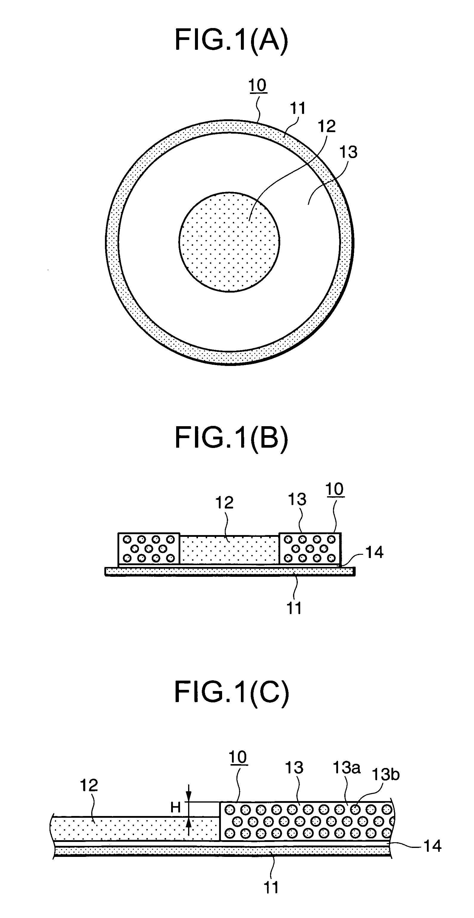
[0027]FIGS. 1(A) through 1(C) are configurational views of a cleaning sheet for probe needles, showing a first embodiment of the present invention. FIG. 1(A) is a surface view thereof as seen from above, FIG. 1(B) is a vertical cross-sectional view thereof, and FIG. 1(C) is a partly vertical-sectional enlarged view thereof, respectively.

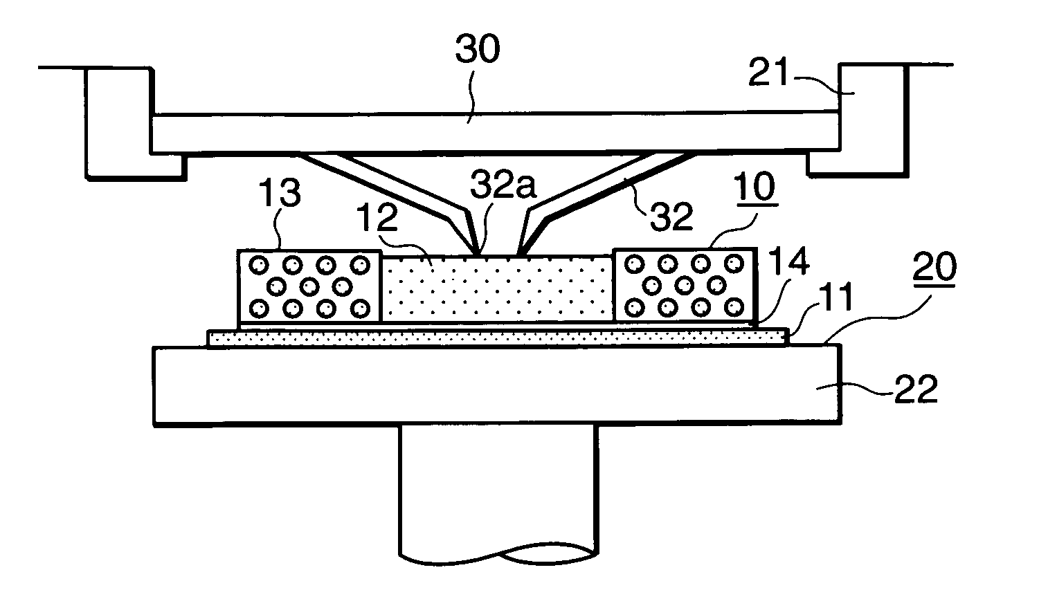
[0028]The cleaning sheet 10 has a disc-shaped substrate 11 such as a wafer. A circular first polishing layer 12 is disposed in a central portion thereof on the substrate 11. A second polishing layer 13 is disposed on a concentric circle at its peripheral portion. These first and second polishing layers 12 and 13 are bonded onto the substrate 11 with an adhesive 14. The first polishing layer 12 has a surface formed in a surface-roughened fashion (e.g., a sandpaper fashion) to polish a tip section of each probe needle and has the function of principally removing adherents leading to inhibition of electrical conduction, which have been ad...

second preferred embodiment

(Configuration)

[0041]FIGS. 3(A) through 3(C) are configurational views of a cleaning sheet for probe needles, showing a second embodiment of the present invention. FIG. 3(A) is a surface view thereof as viewed from above, FIG. 3(B) is a vertical cross-sectional view thereof, and FIG. 3(C) is a partly vertical-sectional enlarged view thereof, respectively.

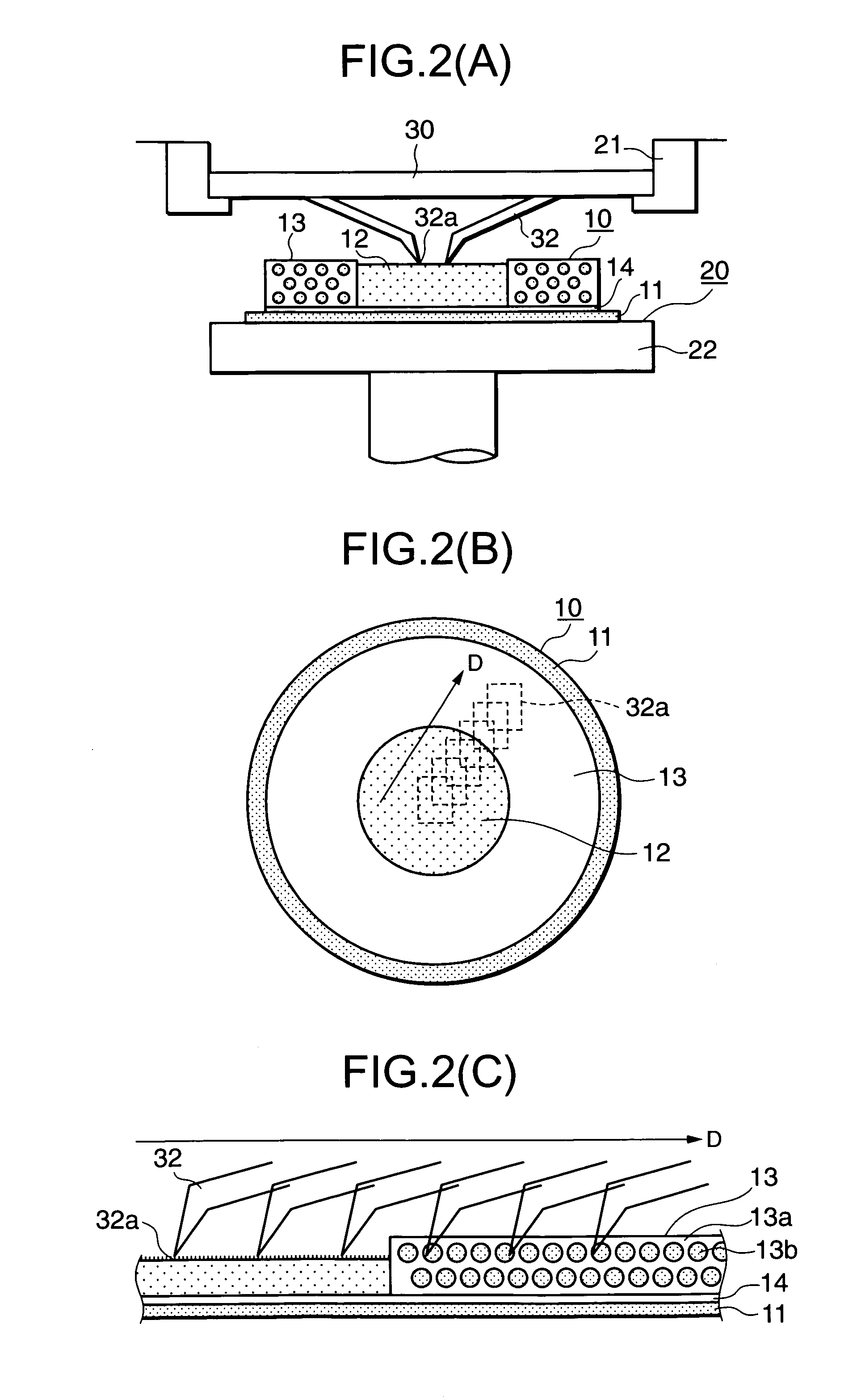
[0042]It is considered that since the area for polishing the tip sections of the probe needles 32 and the area for polishing the whole needlepoints are largely divided into the two like the polishing layer 12 at the central portion of the round sheet and the polishing layer 13 at its peripheral portion in the cleaning sheet 10 according to the first embodiment, the distance over which the probe needles 32 move on the cleaning sheet 10, increases upon executing the polishing and the processing time becomes long. Therefore, the present embodiment is set to a structure having two functions for alternately disposing, at intervals of wid...

third preferred embodiment

[0052]FIG. 5 is a surface view of a cleaning sheet for probe needles showing a third embodiment of the present invention, as viewed from thereabove.

[0053]The present cleaning sheet 10A is a modification of the first embodiment. A semicircular first polishing layer 12A and a semicircular second polishing layer 13A both divided into two are disposed over a disc-shaped substrate 11. These first and second polishing layers 12A and 13A are adhered onto the substrate 11. The first polishing layer 12A has a sandpaper-like surface and polishes the tips of the needlepoints 32a. The second polishing layer 13A is a sponge-like layer containing polishing grains and polishes the whole needlepoints with the needlepoints 32a being stuck therein.

[0054]In a polishing process using the prober 20, the probe needles 32 are moved from the first polishing layer 12A to the second polishing layer 13A and pressed against the second polishing layer 13A. Alternatively, the probe needles 32 are moved from the ...


PUM


Abstract

A cleaning sheet has a disc-shaped substrate. First and second polishing layers are disposed over the substrate. The first polishing layer has a surface formed in a surface-roughened fashion to polish a tip section of each probe needle and has the function of removing adherents leading to inhibition of electrical conduction, which have been adhered to the tip of the needle in a coating or film form. The second polishing layer is a layer in which a large number of polishing grains are mixed into an elastic member and has the function of sticking the tip of the probe needle into the elastic member to remove foreign substances. The height of the surface of the second polishing layer is set so as to become identical to or slightly higher than that of the surface of the first polishing layer.

Description

BACKGROUND OF THE INVENTION[0001]1. Field of the Invention[0002]The present invention relates to a cleaning sheet for probe needles, which is capable of substantially simultaneously polishing and removing both film-like adherents leading to inhibition of contactability of needlepoints of a probe card used to measure and inspect the state of completion of each device on a semiconductor wafer (hereinafter simply called “wafer”) and aluminum chips or the like adhered to the entire needlepoints.[0003]2. Description of the Related Art[0004]The following two types are known as cleaning sheets for polishing needlepoints of general probe cards.[0005]The first type of cleaning sheet is a sheet in which polishing grains are contained in a sponge-like substance. The cleaning sheet can be used in a prober or the like in the same manner as a wafer by being attached to the surface of, for example, a used wafer or the like. Needle tips of a probe card attached to the prober or the like are stuck i...

Claims


Application Information

Patent Timeline
Patent Type & Authority Patents(United States)
IPC IPC(8): B24D11/04B24D11/00B08B1/00G01R31/26B24D3/00G01R1/06H01L21/66
CPCB08B1/00B08B1/008B24D11/04
Inventor MITARAI, KENJI
Owner LAPIS SEMICON CO LTD
Why Eureka
Try Eureka