A brush unit, a device for brush-polishing that uses the brush unit, a system for brush-polishing, and a method for brush-polishing

a brush unit and brush technology, applied in the direction of grinding drives, grinding heads, manufacturing tools, etc., can solve the problems of large power, large brush unit, and possible problems, and achieve the effect of reducing the trouble caused to the brush unit by an overload

Active Publication Date: 2015-12-24
SINTOKOGIO LTD
View PDF29 Cites 11 Cited by
  • Summary
  • Abstract
  • Description
  • Claims
  • Application Information

AI Technical Summary

Benefits of technology

[0005]The first aspect of the present invention relates to a brush unit to polish a surface of a workpiece to be polished by means of a polishing brush that rotates and revolves in the planetary motion. The brush unit comprises a polishing brush wherein tips of the plurality of bristles are exposed from the bottom of the polishing brush. It also comprises a rotating unit that has a mechanism for rotation, a mechanism for driving the rotation, a mechanism for transmitting the force for the rotation, and a mechanism for vertically moving. The mechanism for rotation has a rotating shaft that is connected to the polishing brush at one end, a sliding shaft, through which the rotating shaft is inserted so that the rotating shaft can be rotated, and a holder for rotation, through which the sliding shaft is slidably inserted. The mechanism for driving the rotation generates a force for the rotating for rotating the polishing brush about the rotating shaft. The mechanism for transmitting the force for the rotation transmits the force for the rotating to the rotating shaft. The mechanism for vertically moving moves the polishing brush toward the surface of the workpiece to be polished by means of the sliding shaft. The brush unit further comprises a revolving unit that is combined with the rotating unit. The revolving unit has a mechanism for a revolution, a mechanism for driving the revolution, and a mechanism for transmitting the force for the revolution. The mechanism for the revolution rotates so as to revolve the polishing brush. The mechanism for driving the revolution generates a force for the revolution to revolve the polishing brush. The mechanism for transmitting the force for the revolution transmits the force for the revolution to the mechanism for driving the revolution. The capabilities to polish the workpiece can be tailored to the properties of the workpiece and objects to polish, since both the speed of the rotation and the speed of the revolution can be adjusted. Further, since the rotation and revolution are driven by respective forces for the driving from the separate mechanisms, the loads that are applied to the mechanisms are small, so that any troubles caused to the brush unit by an overload are reduced.

Problems solved by technology

However, a motor that has great power is large, so that the entire device for brush-polishing becomes big.
Further, due to the increase of the speed of the rotation a problem may occur, such as vibrations or a noise.
Thus the motor is subject to a large load.

Method used


Image

  • A brush unit, a device for brush-polishing that uses the brush unit, a system for brush-polishing, and a method for brush-polishing
  • A brush unit, a device for brush-polishing that uses the brush unit, a system for brush-polishing, and a method for brush-polishing
  • A brush unit, a device for brush-polishing that uses the brush unit, a system for brush-polishing, and a method for brush-polishing

Examples


first embodiment

A Brush Unit of a First Embodiment

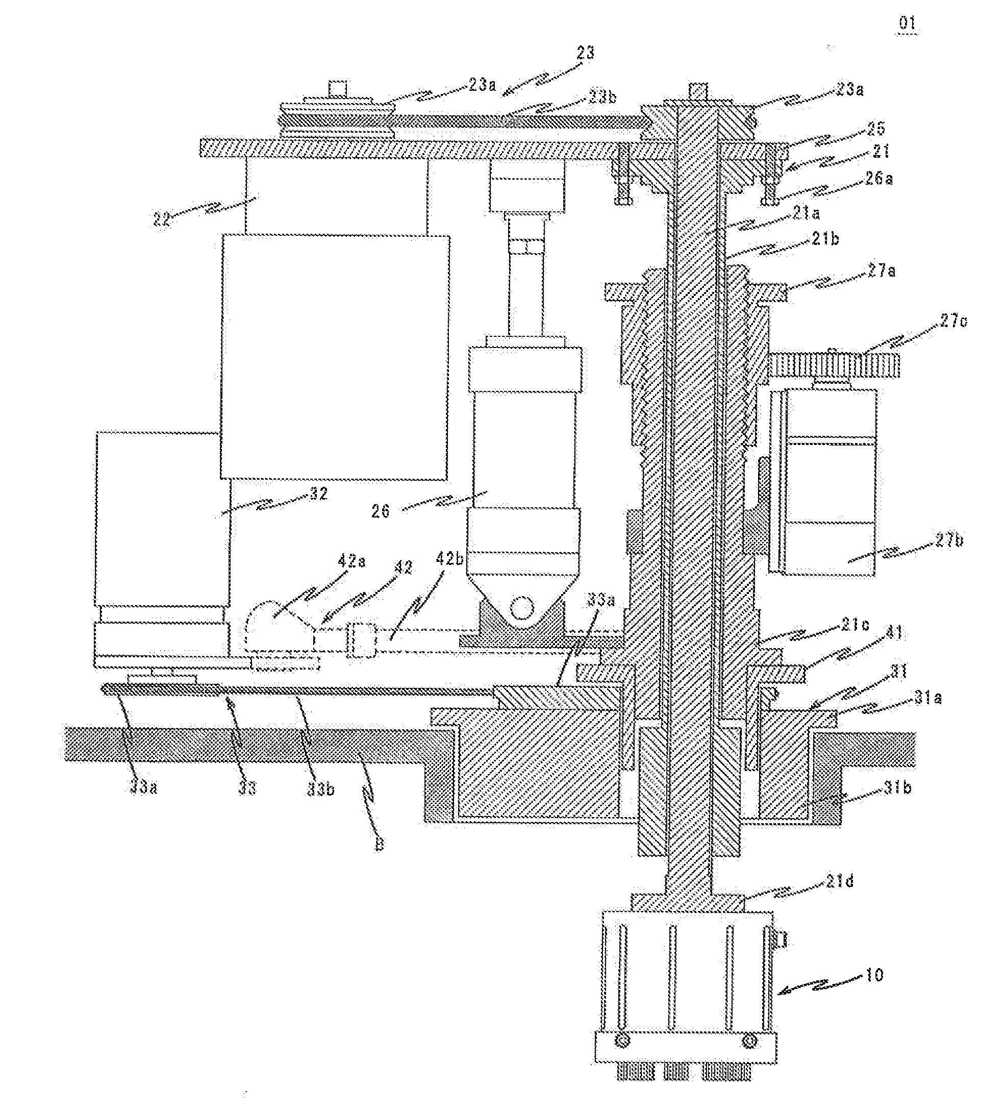
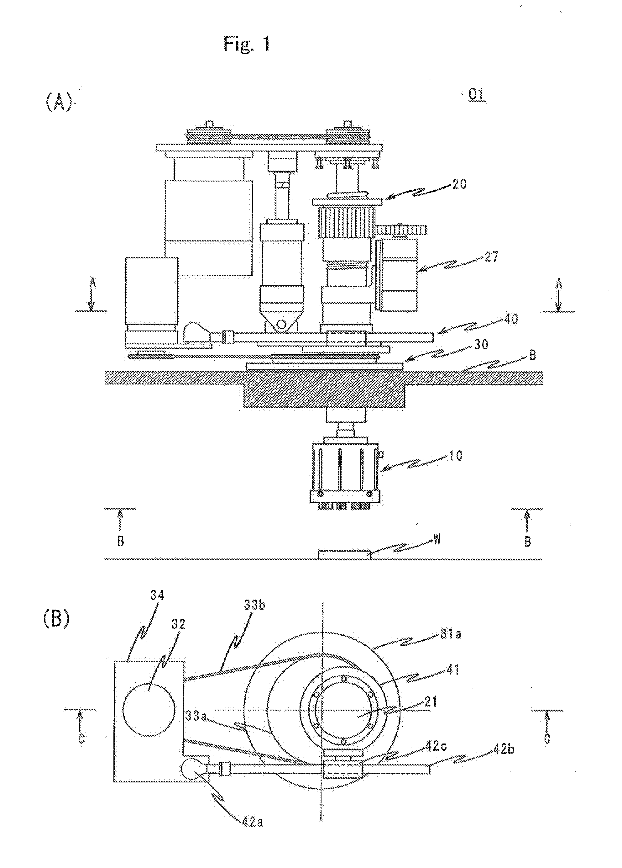
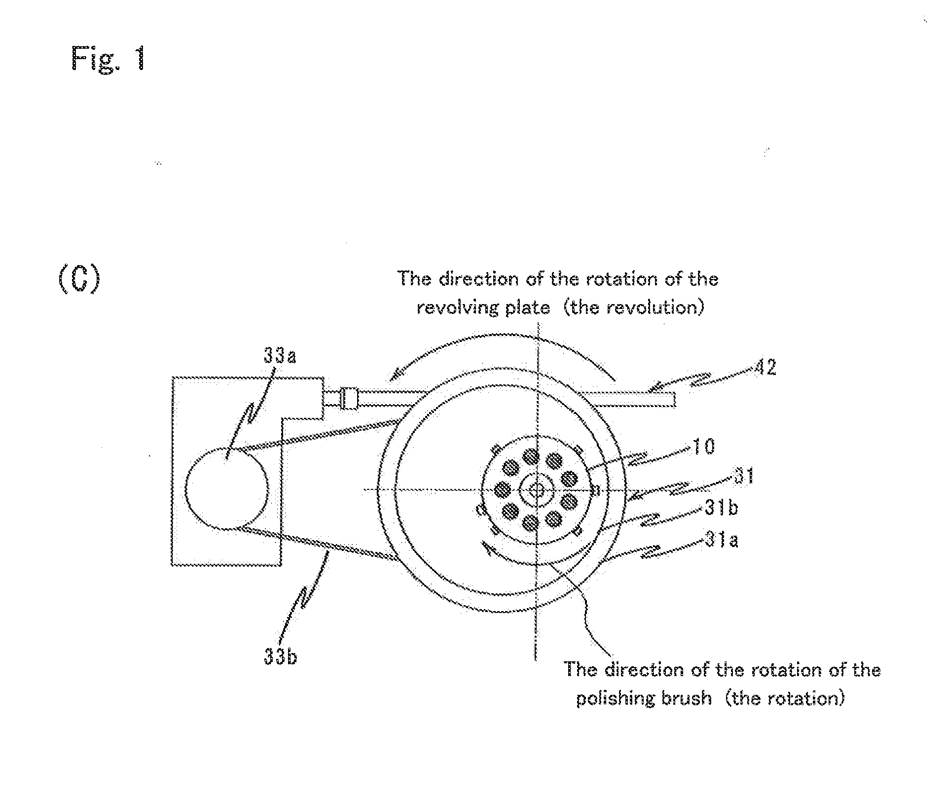
[0032]As in FIGS. 1 to 4, the brush unit 01 of a first embodiment comprises a polishing brush 10, a rotating unit 20, a revolving unit 30, and a connecting unit 40.

[0033]The rotating unit 20 has a mechanism 21 for rotation that is connected to the polishing brush 10, a mechanism 22 for driving the rotation that generates a force for the driving (a force for the rotating) for rotating (for example, horizontally rotating) the polishing brush 10, a mechanism 23 for transmitting the force for the rotation that transmits the force for the rotating to the mechanism 21 for rotation, and a mechanism 26 for vertically moving that lowers the polishing brush 10 toward a workpiece W.

[0034]As in FIG. 2, the mechanism 21 for rotation has a rotating shaft 21a that is approximately a cylindrical column, a sliding shaft 21b that is approximately cylindrical and receives the rotating shaft 21a so that it can be rotated, and a holder for rotation 21c that has a cylind...

second embodiment

A Brush Unit of a Second Embodiment

[0058]Next, with reference to FIGS. 5, 6, and 7, a brush unit 51 of a second embodiment is discussed. The configuration of the second embodiment is the same as that of the first embodiment, unless otherwise indicated.

[0059]As in FIG. 5(A), the brush unit 51 of the second embodiment comprises multiple polishing brushes 60 (four brushes in the present embodiment), a rotating unit 70, a revolving unit 80, and a rack 90.

[0060]The configuration of the polishing brushes 60 is the same as that of the polishing brush 10 of the first embodiment, though there are some differences in the designs, such as their sizes and the number of polishing tools.

[0061]As in FIG. 6, the rotating unit 70 comprises a mechanism 71 for rotation, a mechanism 72 for driving the rotation, a mechanism 73 for transmitting the force for the rotation, a secondary mechanism 74 for transmitting the force for the rotation, and a mechanism 76 for vertically moving. The mechanism 71 for r...

working examples

[0125]The brush unit of the first embodiment and that of the second embodiment are attached to the conveyor-type device for brush-polishing so that the workpieces are polished in various conditions. The results are discussed as working examples. The valve plate that is shown in FIG. 7 and made of steel is used as the workpiece. It is a circular plate 100 mm in diameter and 3.5 mm thick. Ten large holes H1 (10 mm in diameter) or nine small holes H2 (4 mm in diameter) are formed by machining. The corners on both surfaces of these holes are rounded to have r=10-100 μm (R beveling process).

[0126]The workpieces W after being polished are observed by a microscope (KH-3000, available from Hirox, Japan) to evaluate the capabilities to remove burrs, as follows:

[0127]Good: No burrs on any holes

[0128]N.G.: Burrs remain on some holes

[0129]The capabilities to round corners are evaluated by using a contour measuring instrument (2600E, available from Tokyo Seimitsu, Japan) as follows:

[0130]Excelle...


PUM

PropertyMeasurementUnit
diametersaaaaaaaaaa
diameteraaaaaaaaaa
diameteraaaaaaaaaa

Abstract

The purpose of the present invention is to provide a device for brush-polishing by means of a polishing brush that rotates and revolves as in a planetary motion, wherein the conditions to polish can be easily set in accordance with the properties of the workpiece and the purposes to polish. A brush unit has a polishing brush that rotates and revolves. The brush unit includes a mechanism for driving the rotation that rotates the polishing brush and the mechanism for driving the revolution that revolves it. By adjusting the speed of the rotation by the mechanism for driving the rotation the capabilities to polish the workpiece are enhanced. By adjusting the speed of the revolution by the mechanism for driving the revolution the entire workpiece is uniformly polished.

Description

TECHNICAL FIELD[0001]The present invention relates to a brush unit to polish a workpiece (an object to be processed) by a brush (brush-polish a workpiece) for removing burrs, rounding corners, smoothing surfaces, removing microcracks and micropores in surface layers, removing coatings, such as paint, and so on. The present invention also relates to a device for brush-polishing that uses the brush unit and a method for brush-polishing. It also relates to a system for brush-polishing that brush-polishes both sides of a workpiece.BACKGROUND ART[0002]In a conventional device for brush-polishing, a polishing brush is connected to a motor on the bottom of it, wherein bristles having a capability for polishing are fixed. The tips of the bristles contact a workpiece and the center of the polishing brush is horizontally rotated so as to polish the workpiece by the brush (hereafter, just called “polish”) (for example, see the Japanese translation of PCT International Application No. 2001-5083...

Claims


Application Information

Patent Timeline
Patent Type & Authority Applications(United States)
IPC IPC(8): B24B29/00B24B27/00B24D13/14B24B41/047B24B47/12B24B9/00B24B41/00
CPCB24B29/005B24B9/002B24B27/0069B24B27/0076B24D13/145B24B41/005B24B41/047B24B47/12B24B27/0023B24B9/00
Inventor HAYASHI, TSUGUHITOHIRATSUKA, YOUICHIROTANAHASHI, SHIGERU
Owner SINTOKOGIO LTD
Why Eureka
Try Eureka