Light source device, image reading apparatus and image reading method

a light source device and image reading technology, applied in the direction of lighting and heating apparatus, printing, instruments, etc., can solve the problems of poor inability to obtain image data of high quality, and large size of the entire apparatus, so as to prevent the occurrence of moisture condensation and improve assembly efficiency and maintenability.

Inactive Publication Date: 2005-11-01
FUJIFILM CORP +1
View PDF7 Cites 27 Cited by
  • Summary
  • Abstract
  • Description
  • Claims
  • Application Information

AI Technical Summary

Benefits of technology

[0012]The present invention has been accomplished so as to solve the above-described problems. A first object of the present invention is to provide a light source device which can prevent formation of a large-sized device, and a second object thereof is to ...

Problems solved by technology

Therefore, there exists a problem in that image data read at the time before and after variation of temperature may change and image data of high quality cannot be obtained.
As a result, there exists a problem in that an entire apparatus is made larger.
Therefore, there exists a problem in that assembling efficiency and maintenability are poor.
Moreover, the technique disclosed in JP-A No. 7-175035 has a problem in that, when the temper...

Method used


Image

  • Light source device, image reading apparatus and image reading method
  • Light source device, image reading apparatus and image reading method
  • Light source device, image reading apparatus and image reading method

Examples


Embodiment Construction

[0048]An embodiment of the present invention will be hereinafter described in detail with reference to the attached drawings. The following description will be given in a case in which the present invention is applied to a digital laboratory system.

Schematic Structure of the Entire System:

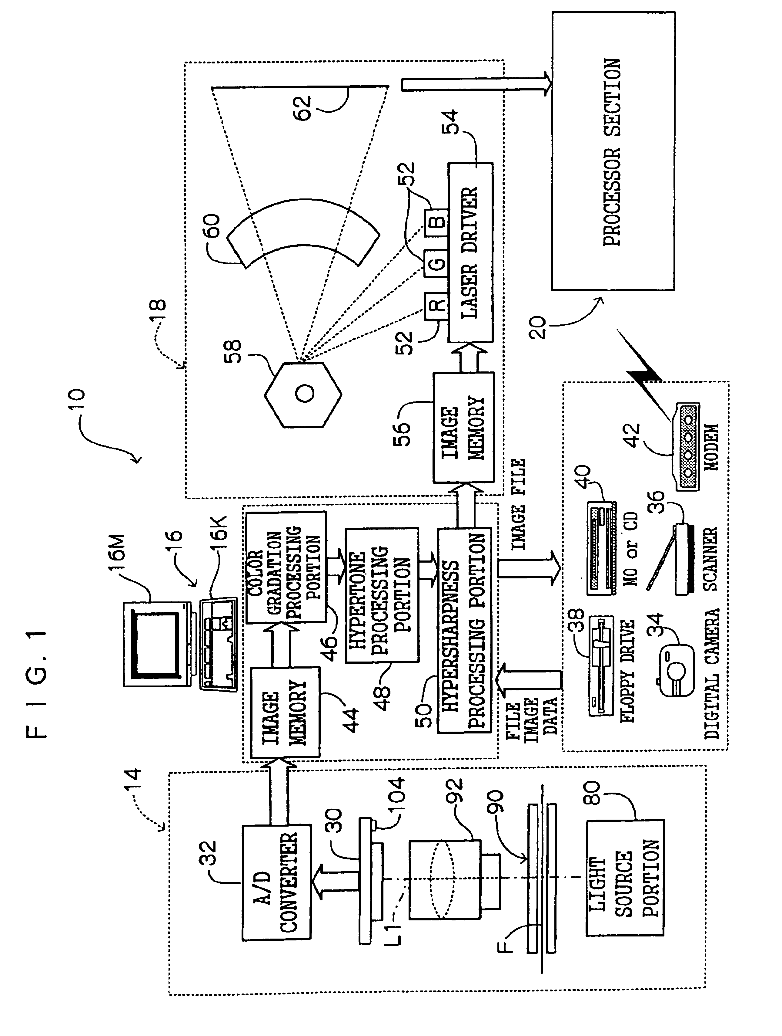
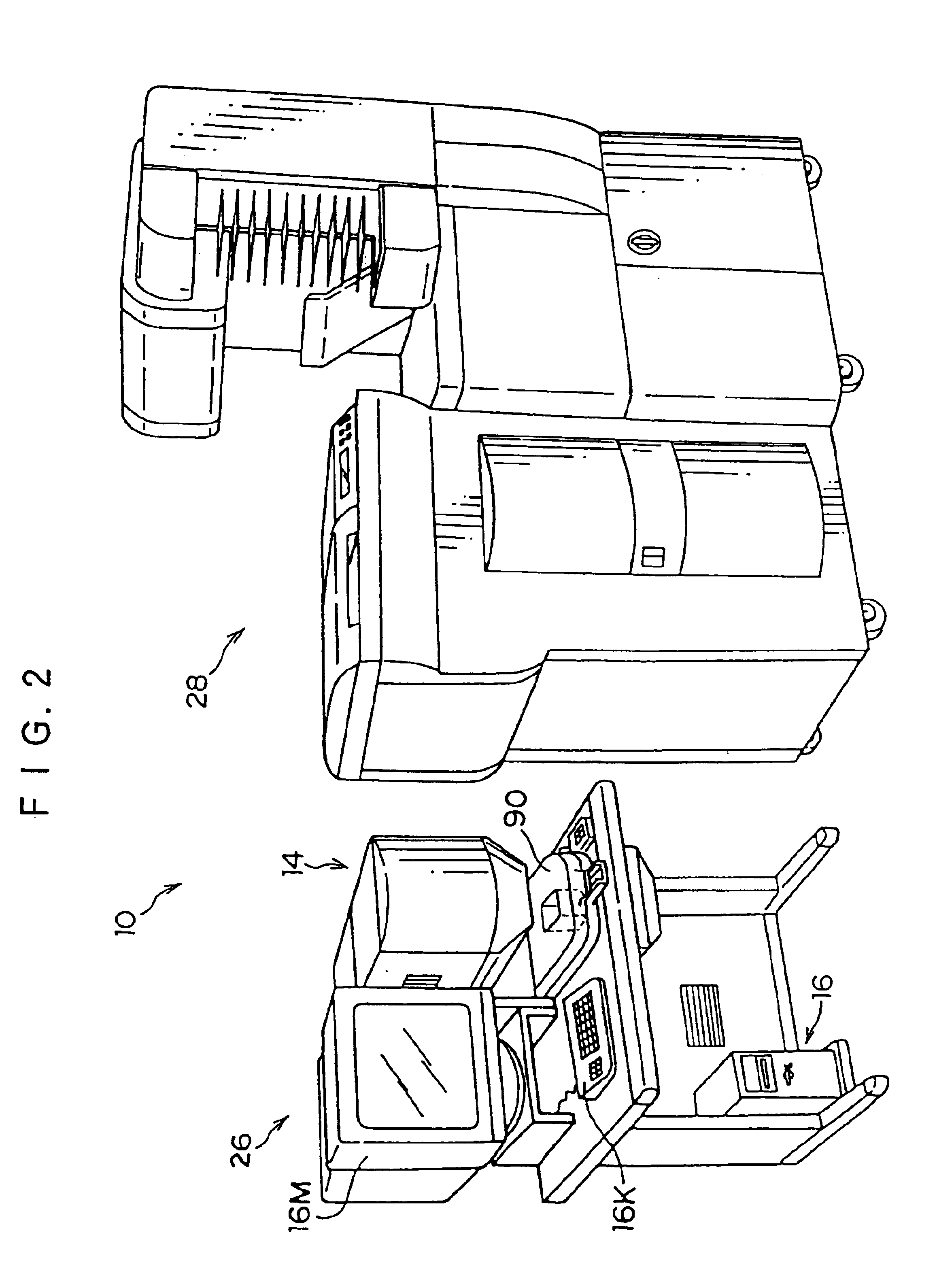
[0049]FIGS. 1 and 2 each show a schematic structure of a digital laboratory system 10 according to the present embodiment.

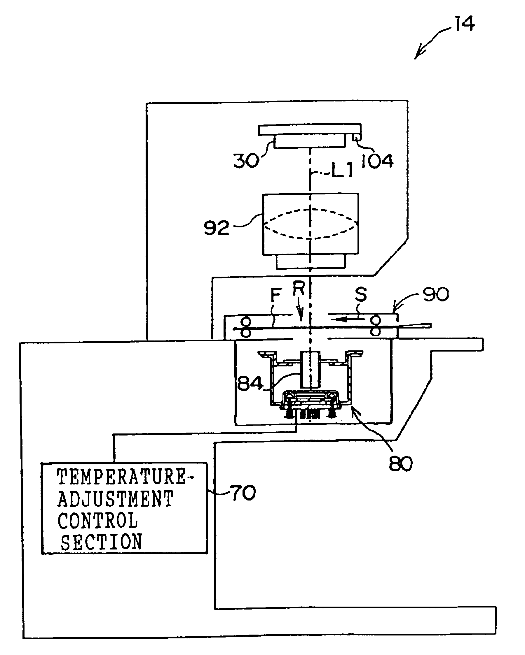
[0050]As shown in FIG. 1, the digital laboratory system 10 is structured so as to include an area CCD scanner section 14, an image processing section 16, a laser printer section 18, and a processor section 20. The area CCD scanner section 14 and the image processing section 16 are integrated as an input section 26 shown in FIG. 2. The laser printer section 18 and the processor section 20 are integrated as an output section 28 shown in FIG. 2.

[0051]The area CCD scanner section 14 is used to read frame images recorded on a photographic film such as a negative film or a reversal fi...


PUM


Abstract

A light source device which can prevent a large-sized structure of the device, a light source device which can improve assembling efficiency and maintainability of the device, and an image forming method and apparatus in which occurrence of moisture condensation can be prevented, are provided. An LED substrate in which a large number of light emitting diodes (LED) are arranged on the surface thereof in a two-dimensional manner, a base, a Peltier element, and a radiating fin are formed integrally by urging force of a compression spring. The radiating fin is disposed in contact with a light source housing body. Further, in carrying out temperature adjustment control using the Peltier element, the temperature adjustment control is carried out only when the internal temperature of the device in which a light source device is provided, is a predetermined temperature or higher.

Description

BACKGROUND OF THE INVENTION[0001]1. Field of the Invention[0002]The present invention relates to a light source device, an image reading apparatus, and an image reading method. In particular, it relates to a light source device which is capable of suppressing change of state of emitted light, resulting from variation of temperature, and an image reading apparatus equipped with the light source device, and also to an image reading method in the image reading apparatus.[0003]2. Description of the Related Art[0004]In recent years, image reading apparatuses have been put to practical use, wherein illuminating light is applied to a reflection original such as a photographic print, or a transmission original such as a photographic film, and reflected light or transmitted light from the original which carries image information to be recorded thereon, is received by an image sensor such as a charge coupled device (CCD) so as to allow reading of an image recorded on the original, and various...

Claims


Application Information

Patent Timeline
IPC IPC(8): H04N1/028H04N1/12H04N1/191H04N1/193G03B27/54G03B27/52G06T1/00H04N1/04
CPCH04N1/00013H04N1/00037H04N1/00082H04N1/00984H04N1/00989H04N1/00992H04N1/02815H04N1/02865H04N1/12H04N1/193H04N2201/02462H04N2201/0404H04N2201/02474H04N2201/02477H04N2201/02485
Inventor KONAGAYA, TATSUYA
Owner FUJIFILM CORP
Why Eureka
Try Eureka