

Electromagnetic actuator and composite electromagnetic actuator apparatus
a composite electromagnetic actuator and actuator technology, applied in the field of electromagnetic actuators, can solve the problems of insufficient inability to achieve sufficient thrust or electromagnetic force, and inability to set the magnetic flux density of the air gap to a high value, etc., and achieves the effects of high performance, high speed, and convenient operation
- Summary
- Abstract
- Description
- Claims
- Application Information
AI Technical Summary
Benefits of technology
Problems solved by technology
Method used
Image

Examples
first embodiment
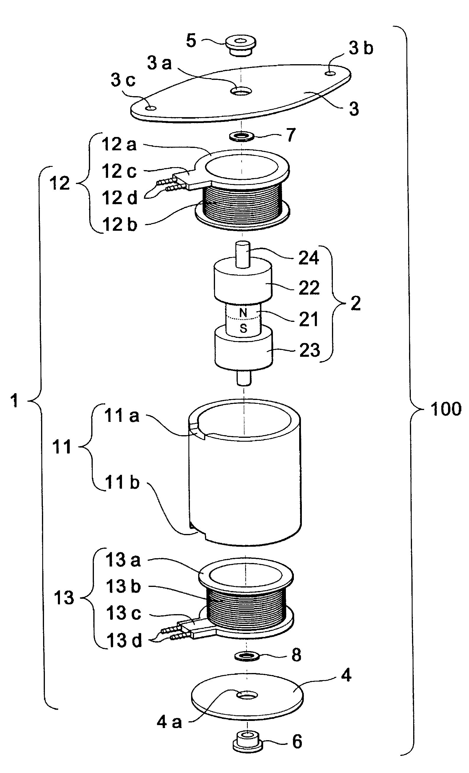
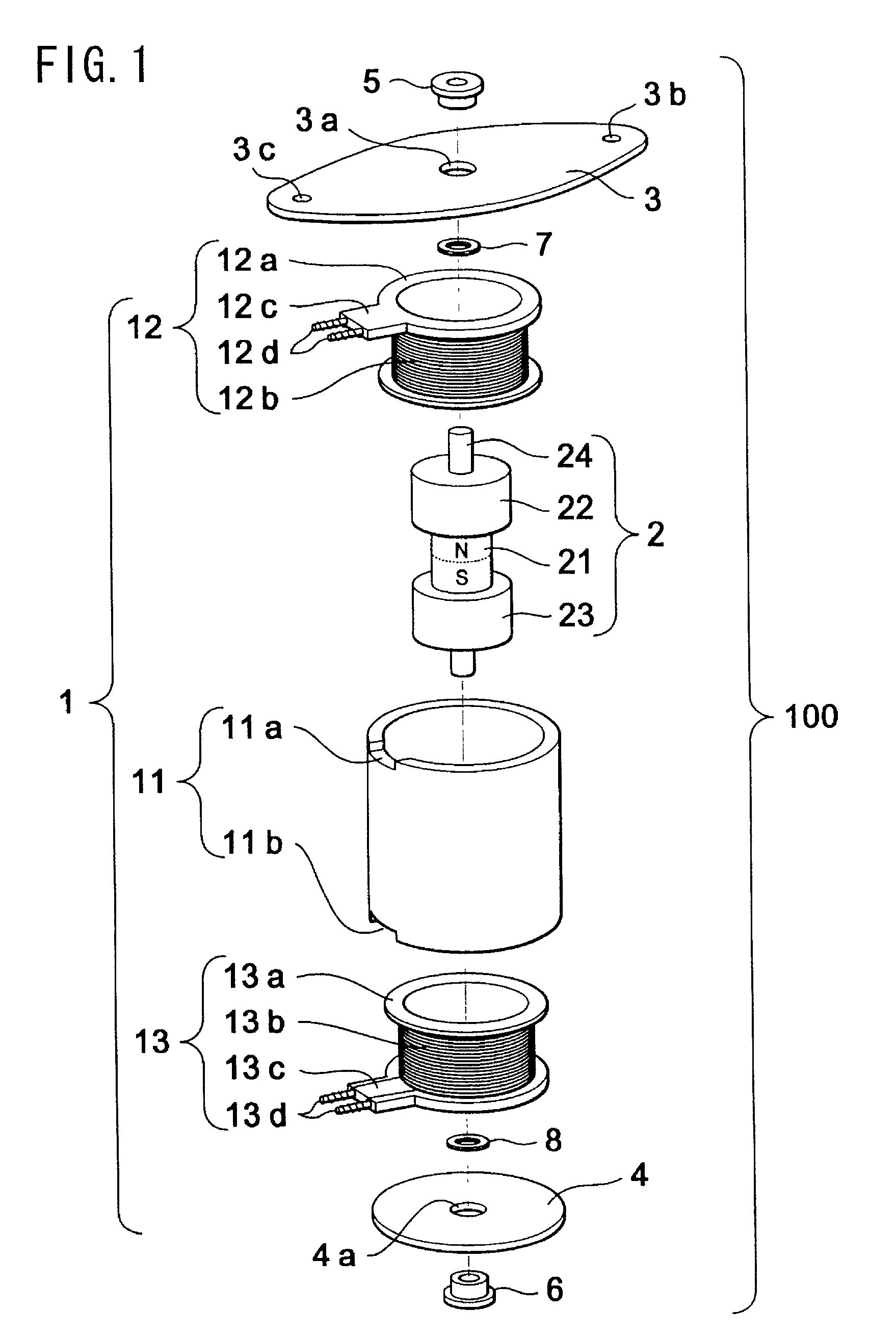
[0044]FIG. 1 is an exploded perspective view showing an electromagnetic actuator in accordance with the present invention. An electromagnetic actuator 100 is roughly divided into a stationary assembly 1, a movable assembly 2, a front flange 3, and a rear flange 4.
[0045]The stationary assembly 1 includes two identical cylindrical coil assemblies 12 and 13 stacked in the axial direction inside a cylindrical stator yoke 11 made of a soft magnetic member (e.g. a galvanized steel plate, a pure iron plate, a resin containing soft magnetic powder, or a sintered compact of soft magnetic powder). The coil assemblies 12 and 13 are of the same structure, and have coils 12b and 13b wound on cylindrical bobbins 12a and 13a, respectively, that are formed of an insulative material, such as a synthetic resin. Terminal blocks 12c and 13c are integrally formed on the flanges of the bobbins 12a and 13a, respectively. Furthermore, wire binding terminals 12d and 13d are implanted in the terminal blocks ...
second embodiment
[0070]An electromagnetic actuator 200 is constituted by a stationary assembly 101 composed of a coil subassembly 112 and a stator yoke 111, a movable assembly 102 composed of a columnar movable magnet 121 and movable yokes 122 and 123 shaped like quadrangular prisms and disposed respectively on both sides of the columnar movable magnet 121 and a supporting shaft 124 penetrating the centers of the above components, a front flange 103 and a rear flange 104. Reference numerals 105 and 106 denote bearings, and reference numerals 107 and 108 denote washers.
[0071]This embodiment is characterized by the structure of the stationary assembly 101. More specifically, the stationary assembly 101 is shaped like a quadrangular prism rather than the round column as in the first embodiment, and the coil subassembly 112 has only one bobbin 112a rather than two. Accordingly, the movable assembly 102 disposed inside the coil subassembly is also shaped like a quadrangular prism.
[0072]The following wil...
PUM
| Property | Measurement | Unit |
|---|---|---|
| travel distance | aaaaa | aaaaa |
| rotation angle | aaaaa | aaaaa |
| travel distance | aaaaa | aaaaa |
Abstract
Description
Claims
Application Information