
Stator for an alternator and method for the manufacture thereof

a technology of stator and alternator, which is applied in the manufacture of stator/rotor bodies, dynamo-electric components, windings, etc., can solve the problems of inability to improve the output of the alternator, inability to short-circuit among the conductor wires, and inability to improve the space factor (the ratio occupied by the conductor wires in the slots), etc., to achieve high space factor, superior electrical insulation, and high dimension precision

Inactive Publication Date: 2005-11-01
MITSUBISHI ELECTRIC CORP
View PDF5 Cites 48 Cited by
  • Summary
  • Abstract
  • Description
  • Claims
  • Application Information

AI Technical Summary

Benefits of technology

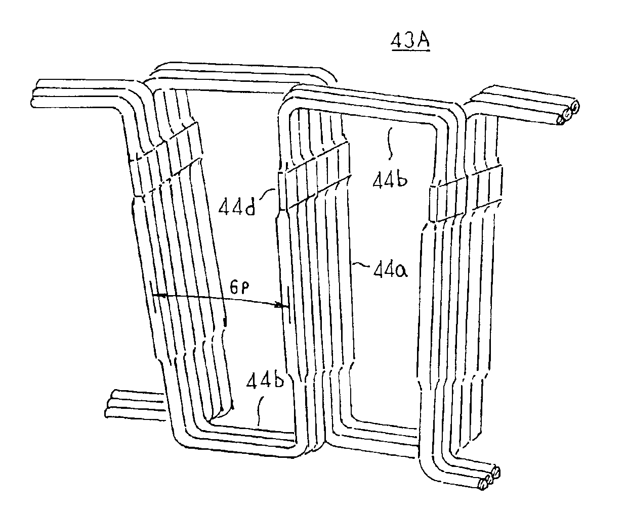
[0024]The present invention aims to solve the above problems and an object of the present invention is to provide a stator for an alternator and a method for the manufacture thereof enabling incidents of short-circuiting among conductor wires to be reduced by constructing a stator winding using distributed windings to distribute coil end portions projecting from any given slot to first and second circumferential sides, and reducing the number of coil end portions linking slot-housed portions in slot pairs to reduce bending stresses resulting from contact between bundles of the coil end portions, thereby suppressing the occurrence of damage to an electrically-insulating coating on the conductor wires.
[0025]Another object of the present invention is to provide a method for manufacturing a stator for an alternator enabling aggravation of electromagnetic noise when mounted to the alternator to be reduced by inserting the slot-housed portions of the stator winding into slots of a stator core from an axial direction and also enabling flange portions to be formed integrally on tips of tooth portions by press punching during formation of the stator core.
[0027]Therefore, the space factor is improved, thereby enabling an alternator having high output to be achieved. Further, the occurrence of damage to the electrically-insulating coating resulting from rubbing among the coil end portions is suppressed and the occurrence of damage to the electrically-insulating coating resulting from bending stresses arising due to contact among the coil end portions is suppressed, thereby providing a stator for an alternator having superior electrical insulation.
[0029]Therefore, a stator having a high space factor and superior electrical insulation can be manufactured. Further, a stator enabling the shape of the tips of the tooth portions to be formed with high dimension precision can be manufactured.

Problems solved by technology

However, one problem has been that improvements in the output of the alternator cannot be achieved when conductor wires having a circular cross section are housed inside the slots because the space factor (the ratio occupied by the conductor wires in the slots) cannot be improved due to space inevitably arising between the conductor wires.
If conductor wires housed in this state are pressed in a slot depth direction, an electrically-insulating coating on the surface of the conductor wires is damaged, giving rise to short-circuiting among the conductor wires.
As a result, another problem has been that the rate of production of the stator declines.
These bending stresses are concentrated at the boundary between the slot-housed portions 12a and the coil end portions 12b and one problem has been that the electrically-insulating coating at the boundary is damaged, giving rise to incidents of short-circuiting among the conductor wires 11.
As a result, another problem has been that when the stator 1 is mounted to an alternator, the magnetic circuit becomes unbalanced, leading to aggravation of electromagnetic noise.

Method used


Image

  • Stator for an alternator and method for the manufacture thereof
  • Stator for an alternator and method for the manufacture thereof
  • Stator for an alternator and method for the manufacture thereof

Examples


embodiment 1

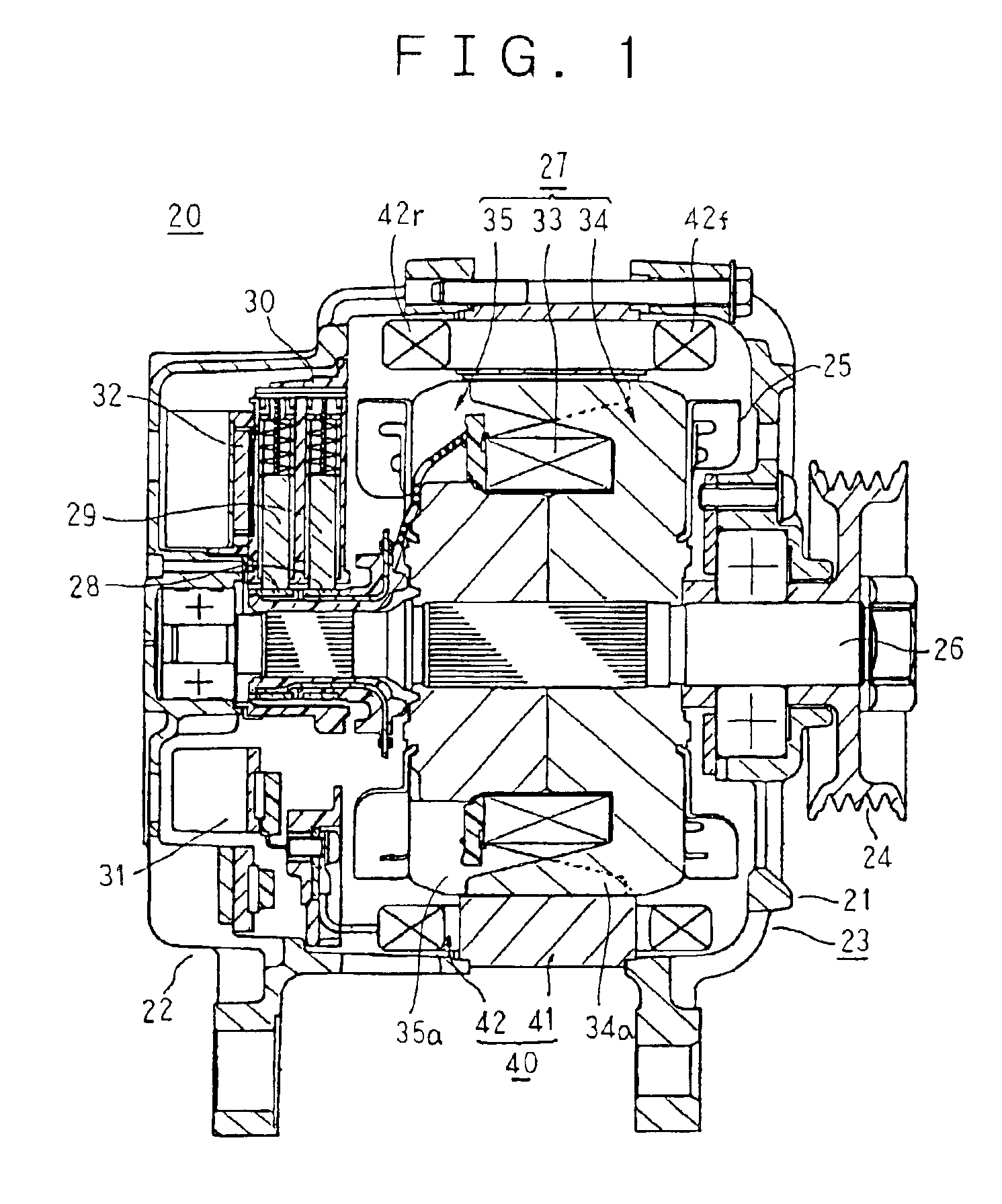
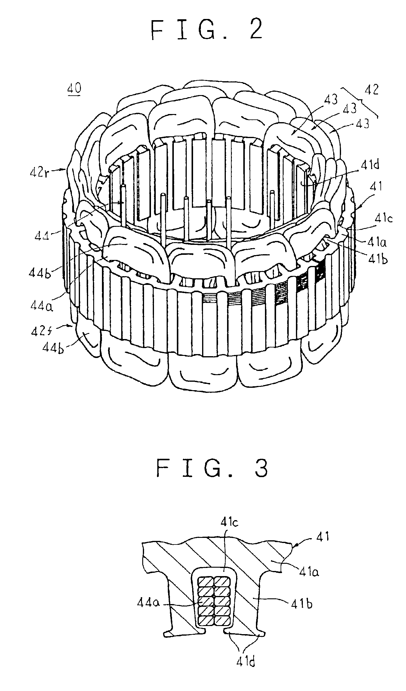
[0065]FIG. 1 is a longitudinal section showing an automotive alternator mounted with a stator according to Embodiment 1 of the present invention, FIG. 2 is a perspective showing the stator for an automotive alternator according to Embodiment 1 of the present invention, and FIG. 3 is a partial cross section showing a slot-housed state of a stator winding in the stator for an automotive alternator according to Embodiment 1 of the present invention.

[0066]As shown in FIG. 1, an automotive alternator 20 includes: a housing 23 constituted by a front bracket 21 and a rear bracket 22 made of aluminum, each being substantially cup-shaped; a shaft 6 disposed inside the housing 23, a pulley 24 being secured to a first end portion of the shaft 26; a Lundell-type rotor 27 secured to the shaft 26; fans 25 secured to first and second axial end portions of the rotor 27; a stator 40 secured to the housing 23 so as to envelop the rotor 27; slip rings 28 secured to a second end portion of the shaft 26...

embodiment 2

[0106]FIG. 9 is a partial cross section showing a slot-housed state of a stator winding in a stator for an automotive alternator according to Embodiment 2 of the present invention.

[0107]In Embodiment 2, slot-housed portions 44c having rectangular cross sections are arranged in five layers so as to line up in two rows in a radial direction inside the slots 41c. The slot-housed portions 44c are formed such that the flatness ratio of each decreases sequentially from the outermost layer to the innermost layer and formed such that bundles of the slot-housed portions 44c arranged in two rows in a radial direction conform to the substantially trapezoidal shape of the slots 41c.

[0108]Moreover, the rest of this embodiment is constructed in a similar manner to Embodiment 1 above.

[0109]According to Embodiment 2, because the slot-housed portions 44c are formed such that the flatness ratio of each decreases sequentially from the outermost layer to the innermost layer and formed such that bundle...

embodiment 3

[0115]In Embodiment 1 above, the star-shaped winding unit 47 is prepared using one conductor wire 44A, but in Embodiment 3, a star-shaped winding unit 49 is prepared using two conductor wires 44A.

[0116]Moreover, the rest of this embodiment is constructed in a similar manner to Embodiment 1 above.

[0117]The process for manufacturing the star-shaped winding unit 49 according to Embodiment 3 will now be explained with reference to FIG. 10.

[0118]First, a annular winding unit 48 is prepared by winding one conductor wire 44A into a ring shape for five turns. Similarly, another annular winding unit 48 is prepared by winding another conductor wire 44A into a ring shape for five turns.

[0119]Next, first and second star-shaped winding sub-units 49A and 49B having a star-shaped pattern in which end portions of adjacent pairs of straight slot-housed portions 49a are alternately linked on an inner circumferential side and an outer circumferential side by U-shaped coil end portions 49b are prepared...


PUM


Abstract

A stator winding is provided with three distributed winding phase portions each constructed by installing a conductor wire in every third slot. Slot-housed portions of the conductor wires are formed with a rectangular cross section and coil end portions are formed with a circular cross section.

Description

BACKGROUND OF THE INVENTION[0001]1. Field of the Invention[0002]The present invention relates to an alternator, and particularly to a stator for an alternator mounted to an automobile, etc., enabling reductions in size and increased output, and to a method for the manufacture thereof.[0003]2. Description of the Related Art[0004]A conventional stator for an alternator is prepared by installing conductor wires having a circular cross section in slots of a stator core, then pressing the conductor wires housed inside the slots in a slot depth direction, and then making the slot openings half-open by flaring the tips of the tooth portions of the stator core to first and second circumferential sides.[0005]However, one problem has been that improvements in the output of the alternator cannot be achieved when conductor wires having a circular cross section are housed inside the slots because the space factor (the ratio occupied by the conductor wires in the slots) cannot be improved due to ...

Claims


Application Information

Patent Timeline
IPC IPC(8): H02K3/12H02K3/28H02K3/50H02K3/04H02K3/34H02K15/02H02K15/04
CPCH02K3/12H02K3/28H02K15/0435H02K15/067H02K3/50H02K15/0485H02K15/02
Inventor OOHASHI, ATSUSHIASAO, YOSHIHITOTAKIZAWA, TAKUSHIOHNISHI, YUKIYOSHIHOSOKAWA, HIROSHI
Owner MITSUBISHI ELECTRIC CORP
Learn More