[0023]Accordingly, it is a general object of the present invention to provide a novel and useful adaptive antenna unit and
terminal equipment in which the problems described above are eliminated.
[0024]Another and more specific object of the present invention is to provide an adaptive antenna unit which improves the transmission and reception characteristics by combining an array
branch structure and a diversity
branch structure, and also enables the size and
power consumption to be reduced, and to provide a
terminal equipment provided with such an adaptive antenna unit.
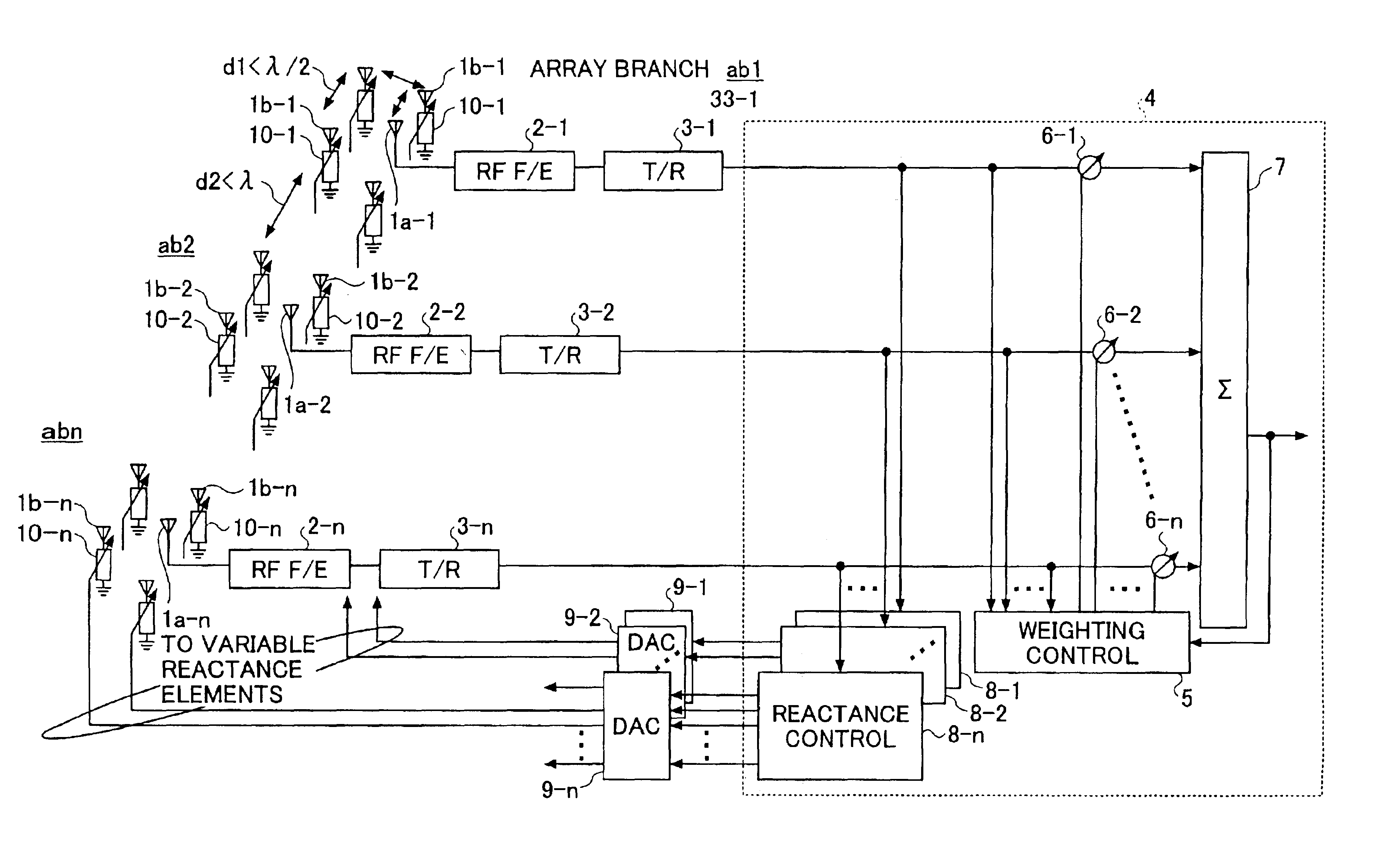
[0025]Still another object of the present invention is to provide an adaptive antenna unit comprising a plurality of feeding antenna elements arranged so as to reduce spatial correlations thereof; a plurality of parasitic antenna elements, provided with respect to each of the plurality of feeding antenna elements, and arranged so as to increase mutual
coupling between a corresponding one of the plurality of feeding antenna elements; a plurality of variable
reactance elements, each terminating a corresponding one of the plurality of parasitic antenna elements; and a control section controlling reactances of the plurality of reactance elements and controlling weighting of the reception signals received by the plurality of feeding antenna elements, in response to the reception signals. According to the adaptive antenna unit of the present invention, it is possible to carry out compensation of the
fading by the diversity branches formed by the feeding antenna elements. In addition, it is possible to suppress interference by forming array branches each formed by one feeding
antenna element and the corresponding parasitic antenna elements. The adaptive antenna unit also has
reduced size and
power consumption due to the relatively simple structure.
[0026]A further object of the present invention is to provide a terminal equipment comprising an adaptive antenna unit; and transmitting and receiving means for making a communication via the adaptive antenna unit, wherein the adaptive antenna unit comprises a plurality of feeding antenna elements arranged so as to reduce spatial correlations thereof; a plurality of parasitic antenna elements, provided with respect to each of the plurality of feeding antenna elements, and arranged so as to increase mutual
coupling between a corresponding one of the plurality of feeding antenna elements; a plurality of variable reactance elements, each terminating a corresponding one of the plurality of parasitic antenna elements; and a control section controlling reactances of the plurality of reactance elements and controlling weighting of the reception signals received by the plurality of feeding antenna elements, in response to the reception signals. According to the terminal equipment of the present invention, it is possible to carry out compensation of the
fading by the diversity branches formed by the feeding antenna elements. In addition, it is possible to suppress interferences by forming array branches each formed by one feeding antenna element and the corresponding parasitic antenna elements. Since the adaptive antenna unit has
reduced size and power consumption due to the relatively simple structure, the terminal equipment may not only be a
base station of a mobile communication
system but also terminals such as a mobile telephone set and a data communication terminal.
[0027]Another object of the present invention is to provide an adaptive antenna unit comprising a plurality of array antenna sections provided at a
pitch greater than a predetermined distance;
a weighting control section weighting and combining output signals of the plurality of array antenna sections; and a controller generating control signals based on the output signals of the plurality of array antenna sections, wherein each of the plurality of array antenna sections comprises a plurality of antenna elements arranged at a
pitch smaller than the predetermined distance; a phase shift part to adjust relative phases of reception signals received by the plurality of antenna elements in response to the control signals; and a combining circuit to combine the reception signals obtained via the phase shift section and outputting the output
signal. According to the adaptive antenna unit of the present invention, it is possible to carry out compensation of the fading by the diversity branches formed by the feeding antenna elements. In addition, it is possible to suppress interference by forming array branches each formed by one feeding antenna element and the corresponding parasitic antenna elements. The adaptive antenna unit also has
reduced size and power consumption due to the relatively simple structure.
[0028]Still another object of the present invention is to provide a terminal equipment comprising an adaptive antenna unit; and transmitting and receiving means for making a communication via the adaptive antenna unit, where the adaptive antenna unit comprises a plurality of array antenna sections provided at a pitch greater than a predetermined distance;
a weighting control section weighting and combining output signals of the plurality of array antenna sections; and a controller generating control signals based on the output signals of the plurality of array antenna sections, wherein each of the plurality of array antenna sections comprises a plurality of antenna elements arranged at a pitch smaller than the predetermined distance; a phase shift part to adjust relative phases of reception signals received by the plurality of antenna elements in response to the control signals; and a combining circuit to combine the reception signals obtained via the phase shift section and outputting the output
signal. According to the terminal equipment of the present invention, it is possible to carry out compensation of the fading by the diversity branches formed by the feeding antenna elements. In addition, it is possible to suppress interferences by forming array branches each formed by one feeding antenna element and the corresponding parasitic antenna elements. Since the adaptive antenna unit has reduced size and power consumption due to the relatively simple structure, the terminal equipment may not only be a
base station of a mobile communication
system but also terminals such as a mobile telephone set and a data communication terminal.

