Combined rankine and vapor compression cycles

Inactive Publication Date: 2005-11-08
CARRIER CORP
View PDF69 Cites 51 Cited by
  • Summary
  • Abstract
  • Description
  • Claims
  • Application Information

AI Technical Summary

Benefits of technology

[0017]Briefly, in accordance with one aspect of the invention, a centrifugal compressor which is designed for compression of refrigerant for purposes of air conditioning, is used in a reverse flow relationship so as to thereby operate as a tur

Problems solved by technology

The turbines in such systems are designed to operate at relatively high pressures and high temperatures and are relatively expensive in their manufacture and use.
With the advent of the energy crisis and, the need to conserve, and to more effectively use, our available energies, rankine cycle systems have been used to capture the so called “waste heat”, that was otherwise being lost to the atmosphere and, as such, was indirectly detrimental to the environment by requiring more fuel for power production than necessary.
While the combustion products of methane (CO2 and H2O) do less ha

Method used


Image

  • Combined rankine and vapor compression cycles
  • Combined rankine and vapor compression cycles
  • Combined rankine and vapor compression cycles

Examples


Embodiment Construction

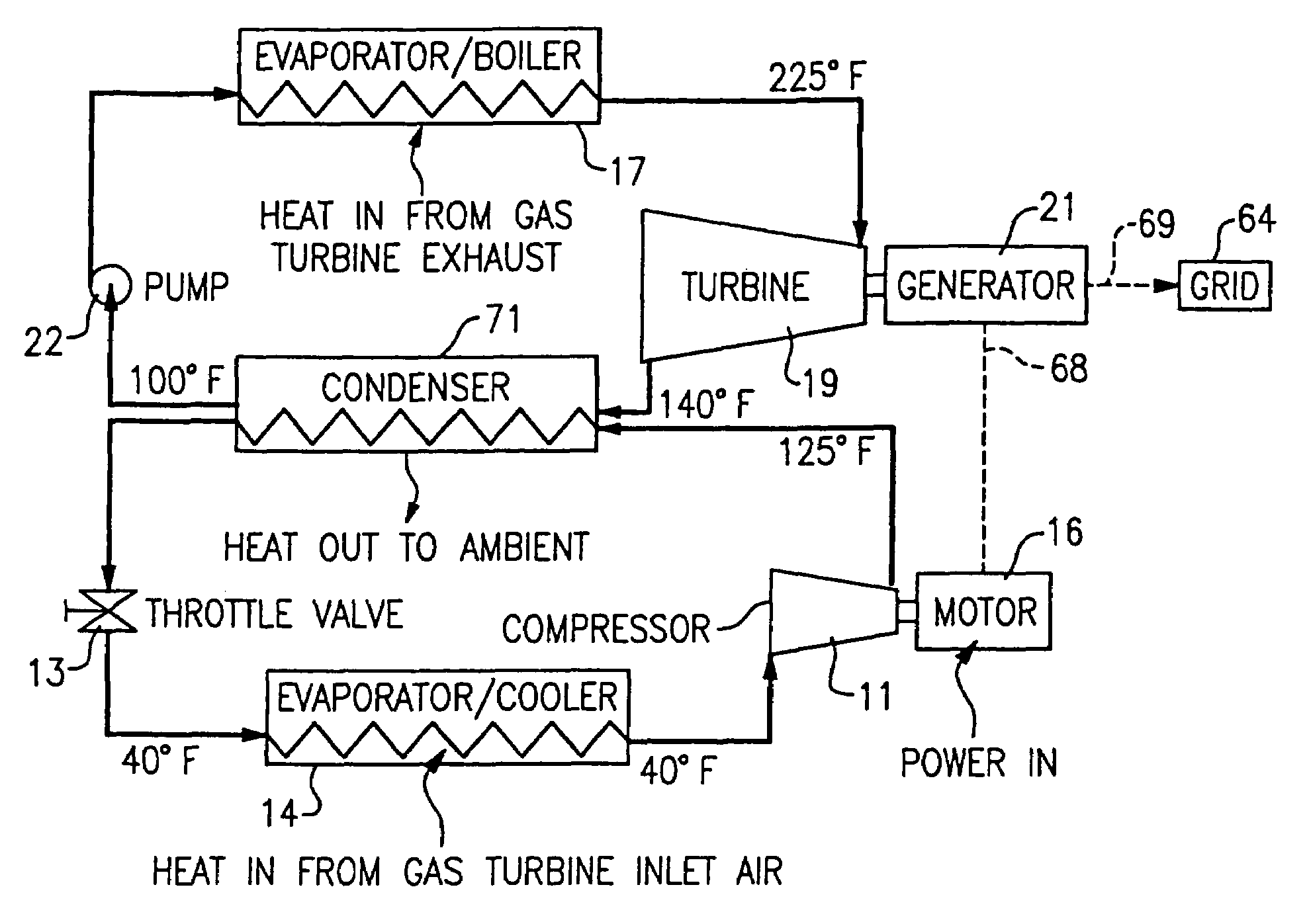
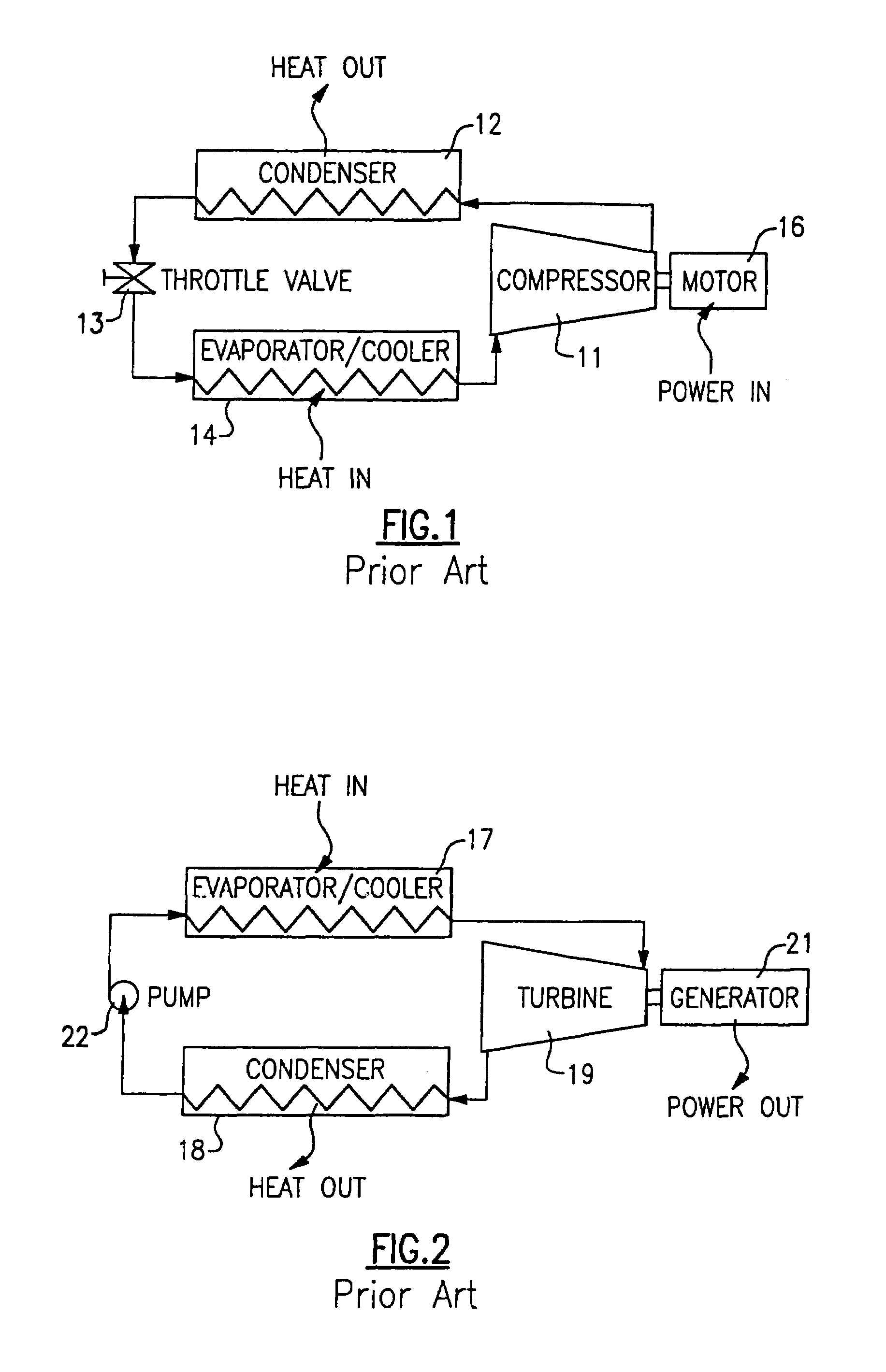
[0039]Referring now to FIG. 1, a typical vapor compression cycle is shown as comprising, in serial flow relationship, a compressor 11, a condenser 12, a throttle valve 13, and an evaporator / cooler 14. Within this cycle a refrigerant, such as R-11, R-22, or R-134a is caused to flow through the system in a counterclockwise direction as indicated by the arrows.

[0040]The compressor 11 which is driven by a motor 16 receives refrigerant vapor from the evaporator / cooler 14 and compresses it to a higher temperature and pressure, with the relatively hot vapor then passing to the condenser 12 where it is cooled and condensed to a liquid state by a heat exchange relationship with a cooling medium such as air or water. The liquid refrigerant then passes from the condenser to a throttle valve wherein the refrigerant is expanded to a low temperature two-phase liquid / vapor state as it passes to the evaporator / cooler 14. The evaporator liquid provides a cooling effect to air or water passing throug...


PUM


Abstract

An organic rankine cycle system is combined with a vapor compression cycle system with the turbine generator of the organic rankine cycle generating the power necessary to operate the motor of the refrigerant compressor. The vapor compression cycle is applied with its evaporator cooling the inlet air into a gas turbine, and the organic rankine cycle is applied to receive heat from a gas turbine exhaust to heat its boiler within one embodiment, a common condenser is used for the organic rankine cycle and the vapor compression cycle, with a common refrigerant, R-245a being circulated within both systems. In another embodiment, the turbine driven generator has a common shaft connected to the compressor to thereby eliminate the need for a separate motor to drive the compressor.

Description

CROSS REFERENCE TO RELATED APPLICATIONS[0001]This application is a divisional of U.S. Ser. No. 10 / 293,712, filed Nov. 13, 2002, now U.S. Pat. No. 6,892,522, which is incorporated herein by reference.BACKGROUND OF THE INVENTION[0002]This invention relates generally to organic rankine cycle systems and, more particularly, to an economical and practical method and apparatus therefor.[0003]The well known closed rankine cycle comprises a boiler or evaporator for the evaporation of a motive fluid, a turbine fed with vapor from the boiler to drive the generator or other load, a condenser for condensing the exhaust vapors from the turbine and a means, such as a pump, for recycling the condensed fluid to the boiler. Such a system as is shown and described in U.S. Pat. No. 3,393,515.[0004]Such rankine cycle systems are commonly used for the purpose of generating electrical power that is provided to a power distribution system, or grid, for residential and commercial use across the country. Th...

Claims


Application Information

Patent Timeline
IPC IPC(8): F01K23/10F01K23/06F01K23/08F02C6/18F25B27/00
CPCF02C6/18F25B27/00F25B27/02F01D15/005F01K23/08F01K23/10F25B2400/14Y02E20/16Y02A30/274
Inventor BRASZ, JOOST J.BIEDERMAN, BRUCE P.
Owner CARRIER CORP
Why Eureka
Try Eureka