System and method for measuring a horizontal deviation of a load receiving element

Inactive Publication Date: 2005-11-08
KRUSCHE LAGERTECHN
View PDF13 Cites 16 Cited by
  • Summary
  • Abstract
  • Description
  • Claims
  • Application Information

AI Technical Summary

Benefits of technology

[0014]Particularly advantageous are the small dimensions of the cable length sensors and their anchorage points, the high accuracy of measurement and sampling rate as well as the high ease of maintenance of the system according to the invention.
[0020]The system according to the invention is based on the realization that when using at least two cable length sensors which are disposed respectively on the hoist traveling trolley and / or respectively on the load receiving element, the horizontal deviation of the load receiving element effectuates a shortening of the length of cable in the case of at least one of the cable length sensors, wherein this horizontal deviation effectuates a lengthening of the length of cable in the case of at least one other the cable length sensor. To this effect, the at least two cable length sensors are advantageously disposed on the hoist traveling trolley or respectively on the load receiving element in such a way that the two cables of at least two of the cable length sensors are intersecting.
[0024]It has proved particularly advantageous for the two cable length sensors to be arranged in such a way that a maximum possible distance exists between the two cable length sensors. Such a maximum distance produces the greatest possible difference in the lengths of the two cables and therefore increases the accuracy of the measurement result.

Problems solved by technology

This deviation occurs regularly during transportation of the loads suspended from the supporting cables, with the consequence that an undesirable oscillation of the loads attached to the supporting cables will be initiated during a steady movement of the hoist traveling trolley.
In the worst case, there will be a higher risk of collisions and accidents.
A drawback of the CeSAR system by CePLuS has been that the time intervals for determining the deviation are too large for realtime dynamic control, and further, the resolution with regard to the accuracy of measurement of the camera measurement system is insufficient to meet the demands of the realtime dynamic control.
In addition to this detrimental system data, the overall size of the CeSAR oscillation damping system has proved to be disadvantageous, since the reflectors which must be attached to the load receiving element have unfavourable dimensions.
A further drawback of the CeSAR system is the limited field of view if at least a certain degree of measurement accuracy is required to be achieved, as the accuracy of measurement of the camera lens correlates to the horizontal field angle.
A large horizontal field angle requires, therefore, a so-called wide angle lens which, however, is detrimental to image resolution and, ultimately, accuracy of measurement.
One more drawback of the CeSAR system is the frequency of maintenance required by the optical devices.
This is because during usage in conventional storage environments, a certain degree of contamination of the racks, goods to be and, consequently, the means of transport is to be expected at regular intervals, with the result that the optical devices, such as the camera lens, will have to be cleaned frequently.

Method used


Image

  • System and method for measuring a horizontal deviation of a load receiving element
  • System and method for measuring a horizontal deviation of a load receiving element
  • System and method for measuring a horizontal deviation of a load receiving element

Examples


Embodiment Construction

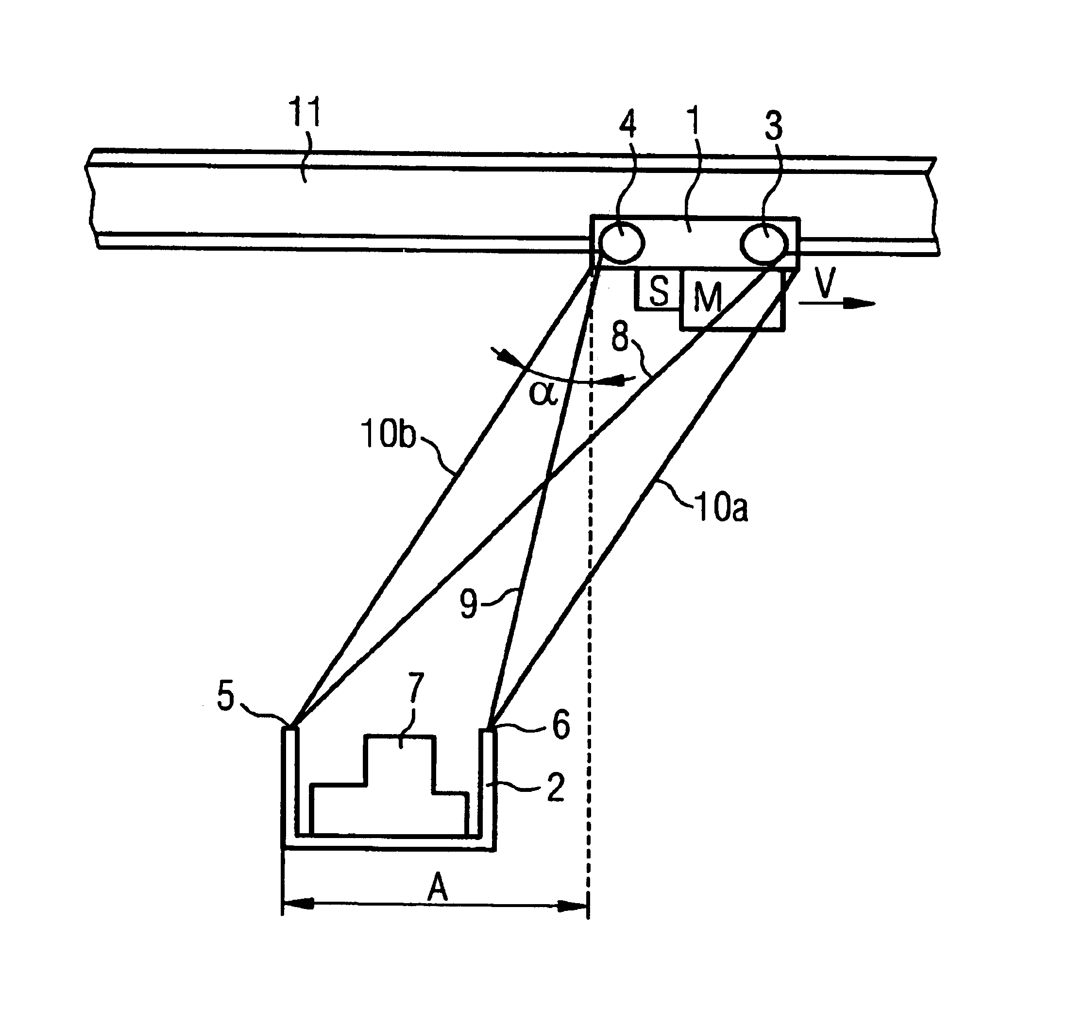
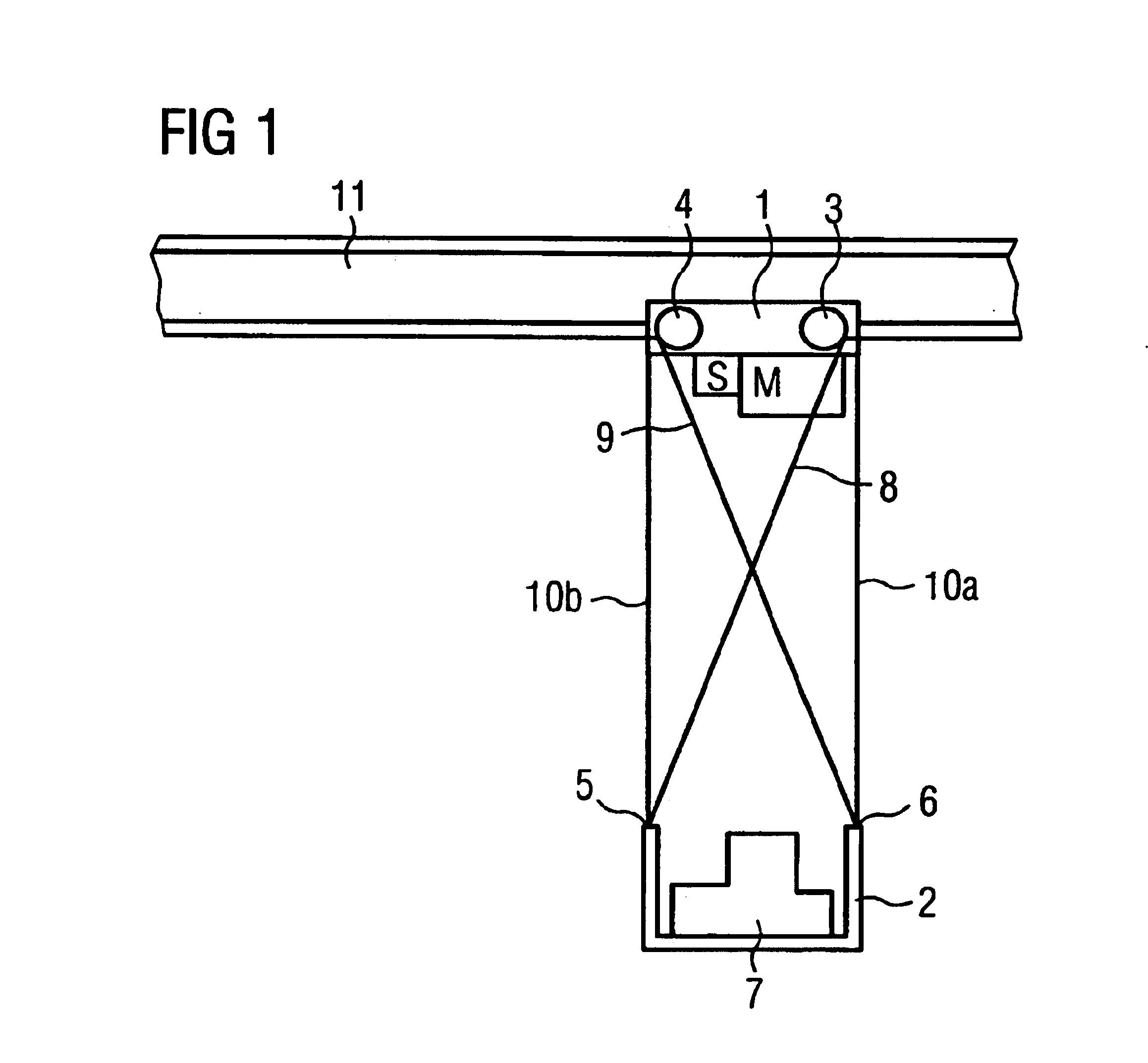
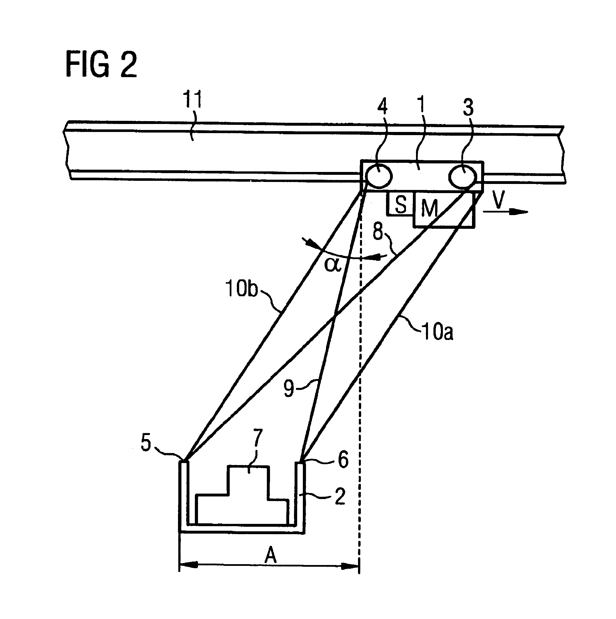
[0030]FIG. 1 shows a system according to the invention consisting of a hoist travelling trolley 1 which is driven by a motor M for the purpose of transportation on rail 11. The power supply to the motor M is not shown. Motor M is controlled via a control unit S which is operatively connected to the motor M, but need not necessarily be arranged on the hoist travelling trolley. A data processing means, preferably a processor with a computer unit in which corresponding mathematical algorithms are stored, is integrated in or at least connected to the control unit. In the preferred embodiment shown in FIG. 1, there are arranged on the hoist travelling trolley 1 two cabl length sensors 3,4 whos cables 8, 9 are stretched diagonally downwards towards the load receiving element and are secured there at an anchorage point 5,6. The length of cables 8 and 9 is essentially the same in the rest position in FIG. 1 since, due to gravity, the load receiving element 2 is suspended perpendicularly by ...


PUM


Abstract

The aim of the invention is to provide a system and a method which surmounts the problems of prior art. According to the inventive system and method for measuring horizontal deviation of a load receiving element in relation to a position of a hoist traveling trolley, the load receiving element is suspendedly arranged on a plurality of supporting cables on the hoist traveling trolley and least two cable length sensors are provided, the sensors being operatively connected to a data processing device, preferably a processor. The cables of the at least two cable length sensors are disposed between the hoist traveling trolley and the load receiving element in such a way that a computer unit which is connected to the data processing device determines the horizontal deviation of the load receiving element in relation to the position of the hoist traveling trolley for the length of the respective cables of the cable length sensors.

Description

RELATED APPLICATION[0001]This application is a continuation of pending International Patent Application No. PCT / EP02 / 05102 filed May 8, 2002, which designates the United States and claims priority of pending German Application No. 10122142.8 filed May 8, 2001.BACKGROUND OF THE INVENTION[0002]The aim of the present invention is to provide a system from a horizontal deviation of a load receiving element in relation to a position of a hoist travelling trolley, wherein the load receiving element being suspendedly arranged on a plurality of supporting cables on the hoist travelling trolley, as well as a method for measuring a horizontal deflection of a load receiving element in relation to a position of a hoist travelling trolley, wherein the load receiving element being suspendedly arranged on a plurality of supporting cables on the hoist travelling trolley.[0003]During the transportation of loads by bridge crane or gantry crane, ship unloader, girder bridge cranes, as well as coil and ...

Claims


Application Information

Patent Timeline
IPC IPC(8): B66C13/04B66C13/06
CPCB66C13/063
Inventor LUKAS, GUNTHER
Owner KRUSCHE LAGERTECHN
Why Eureka
Try Eureka