Method for removing condensables from a natural gas stream, at a wellhead, downstream of the wellhead choke

a technology of natural gas stream and condensables, which is applied in the direction of auxillary pretreatment, separation process, and wellbore/well accessories. it can solve the problems of not being able not being able to lower the dew point temperature of the produced gas, and being unable to remove water from the wellbore. it requires complex equipment and instrumentation

Inactive Publication Date: 2005-11-08
TWISTER BV +1
View PDF58 Cites 98 Cited by
  • Summary
  • Abstract
  • Description
  • Claims
  • Application Information

AI Technical Summary

Problems solved by technology

This device is only capable of keeping liquid water out of produced gas.
It is not capable of neither removing water from the wellbore, nor from lowering the dew point temperature of the produced gas.
Separators that are effective to lower dew points of gases generally require complex equipment and instrumentation, such as refrigerated sponge oils or glycol absorbers.
Such operations are generally too complex to be placed at wellheads such as sea floor wellheads, and too expensive to be place at individual wellheads in a gas producing field.
However, none describe or hint at their use as part of a wellhead assembly downstream of a wellhead choke.

Method used


Image

  • Method for removing condensables from a natural gas stream, at a wellhead, downstream of the wellhead choke
  • Method for removing condensables from a natural gas stream, at a wellhead, downstream of the wellhead choke
  • Method for removing condensables from a natural gas stream, at a wellhead, downstream of the wellhead choke

Examples


example

[0055]A test device for the present invention was prepared, and demonstrated for separating water vapor from air at ambient conditions. Obviously, in case the device is used subsurface, sub-sea or at the wellhead, different temperatures pressures and Mach numbers may apply. However, a skilled man will have no difficulty making the necessary adaptations. FIG. 4 is referred to for the general configuration of the device used. MDO9 / THl457PCT

[0056]In this example the air 425 was pressurized to 140 KPa (1.4 bar (a)) by means of a blower 401 to provide pressurized air 426. After the blower the air was cooled to about 25 to 30° C. by fin cooler 402, located in a vessel 418, and water 419 was sprayed into the vapor space below the cooler 420 to ensure that the air was near water saturation (RV=90%). This water saturated air 427 was fed to the feed liquid-vapor separator 403 where the water was separated with a small amount of slip air into a wet stream 421, coming along with this water liqu...


PUM

PropertyMeasurementUnit
pressureaaaaaaaaaa
temperatureaaaaaaaaaa
inlet diameteraaaaaaaaaa

Abstract

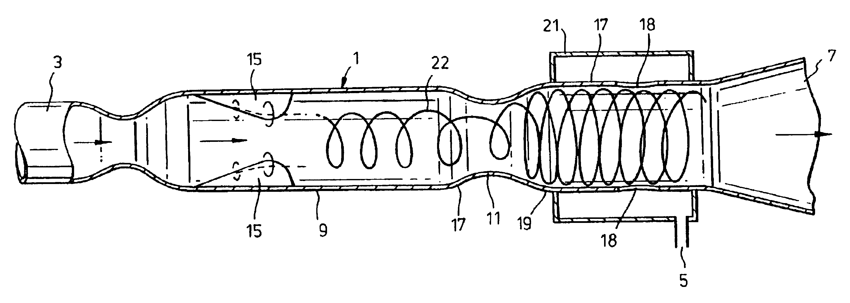
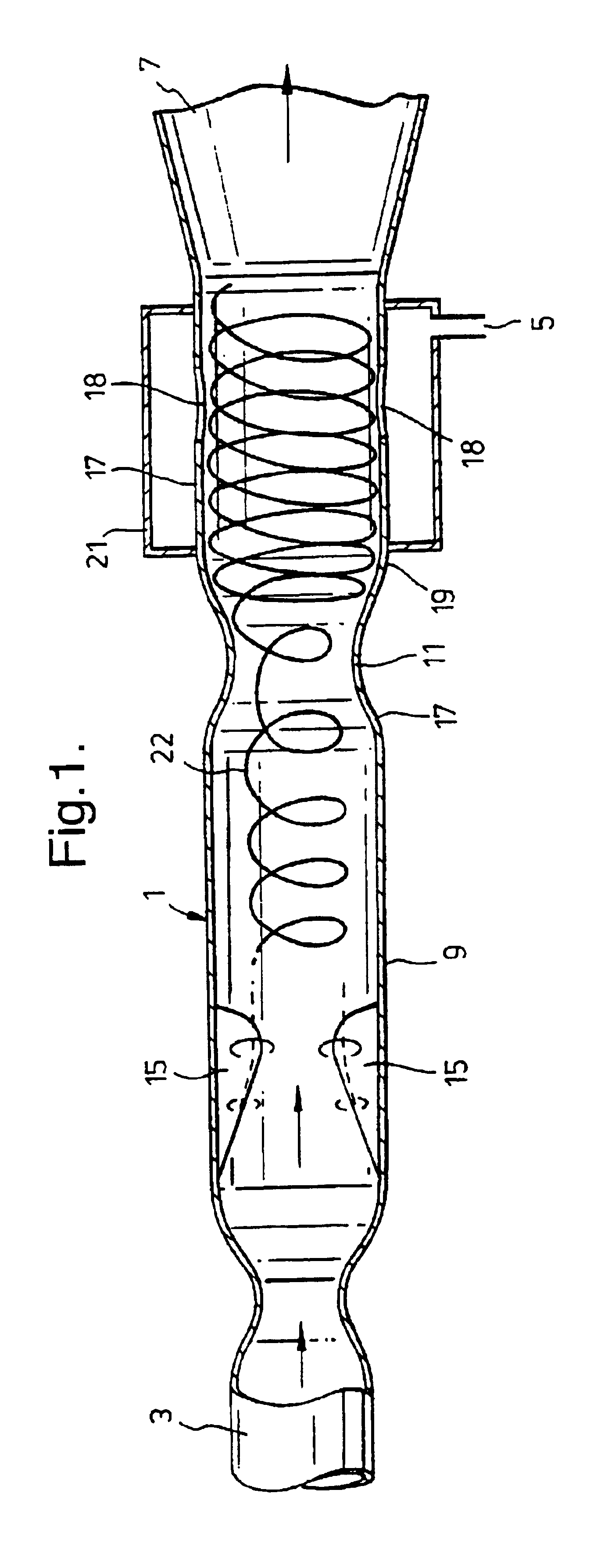
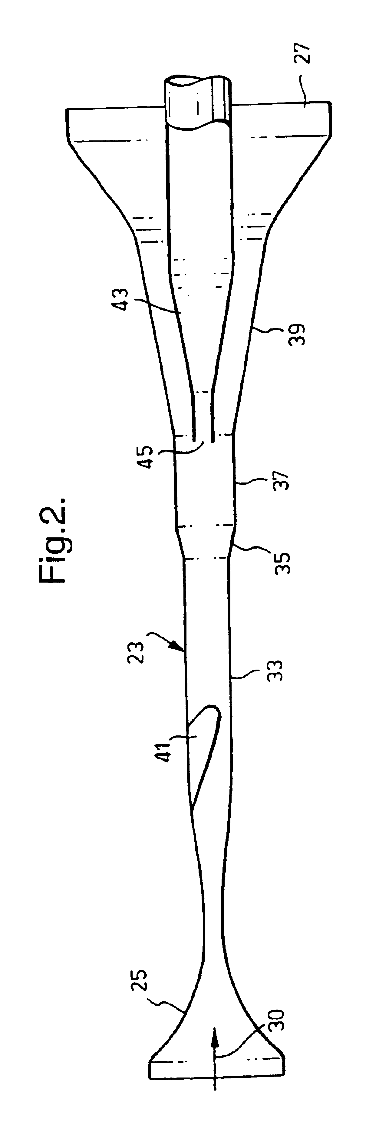
The present invention relates to a method for removing condensables from a natural gas stream, at a wellhead, downstream of the wellhead choke thereof. In accordance with the invention there is provided a method for removing condensables from a natural gas stream at a wellhead, the method comprising the steps of: (A) inducing the natural gas stream to flow at supersonic velocity through a conduit of a supersonic inertia separator and thereby causing the fluid to cool to a temperature that is below a temperature/pressure at which the condensables will begin to condense, forming separate droplets and/or particles; (B) separating the droplets and/or particles from the gas; and (C) collecting the gas from which the condensables have been removed, wherein the supersonic inertia separator is part of the wellhead assembly downstream of the wellhead choke. There is also provided a device for removing said condensables from said natural gas that is part of the wellhead assembly downstream of the choke, a wellhead assembly comprising said device.

Description

FIELD OF THE INVENTION[0001]The present invention relates to a method for removing condensables from a natural gas stream, at a wellhead, downstream of the wellhead choke thereof; to a wellhead device for removing said condensables from said natural gas that is part of the wellhead assembly downstream of the choke, and to a wellhead assembly comprising said device.BACKGROUND TO THE INVENTION[0002]For background information relating to wellhead assemblies and chokes (or sometimes referred to as valves) thereof, intended to control the flow from the well, reference may be had to the following US patents:[0003]U.S. Pat. No.InventorTitle3,155,401MusolfWell Head Assembly3,297,344HanesConnectors For Well Parts4,194,718Baker et alChoke4,102,401ErbstoesserWell treatment fluiddiversion with low density ball sealers4,606,557CoffeySub-sea Wellhead Connector4,898,235EnrightWellhead apparatus for use with a plungerproduced gas well having a shut-in timer,and method of use thereof[0004]Natural ga...

Claims


Application Information

Patent Timeline
Patent Type & Authority Patents(United States)
IPC IPC(8): B01D45/16B01D45/12B01D51/00B01D51/08B01D53/00E21B43/34E21B43/38F25J3/06
CPCB01D45/16B01D51/08B01D53/002E21B43/385E21B43/35
Inventor TJEENK WILLINK, CORNELIS ANTONIE
Owner TWISTER BV
Why Eureka
Try Eureka