

LED lamp
a technology of led lamps and lampshades, which is applied in the direction of discharge tubes/lamp details, electric discharge lamps, discharge tubes luminescnet screens, etc., can solve the problems of color unevenness, significant color unevenness in the light c, and color unevenness problems, so as to reduce color unevenness
- Summary
- Abstract
- Description
- Claims
- Application Information
AI Technical Summary
Benefits of technology
Problems solved by technology
Method used
Image

Examples
embodiment 1
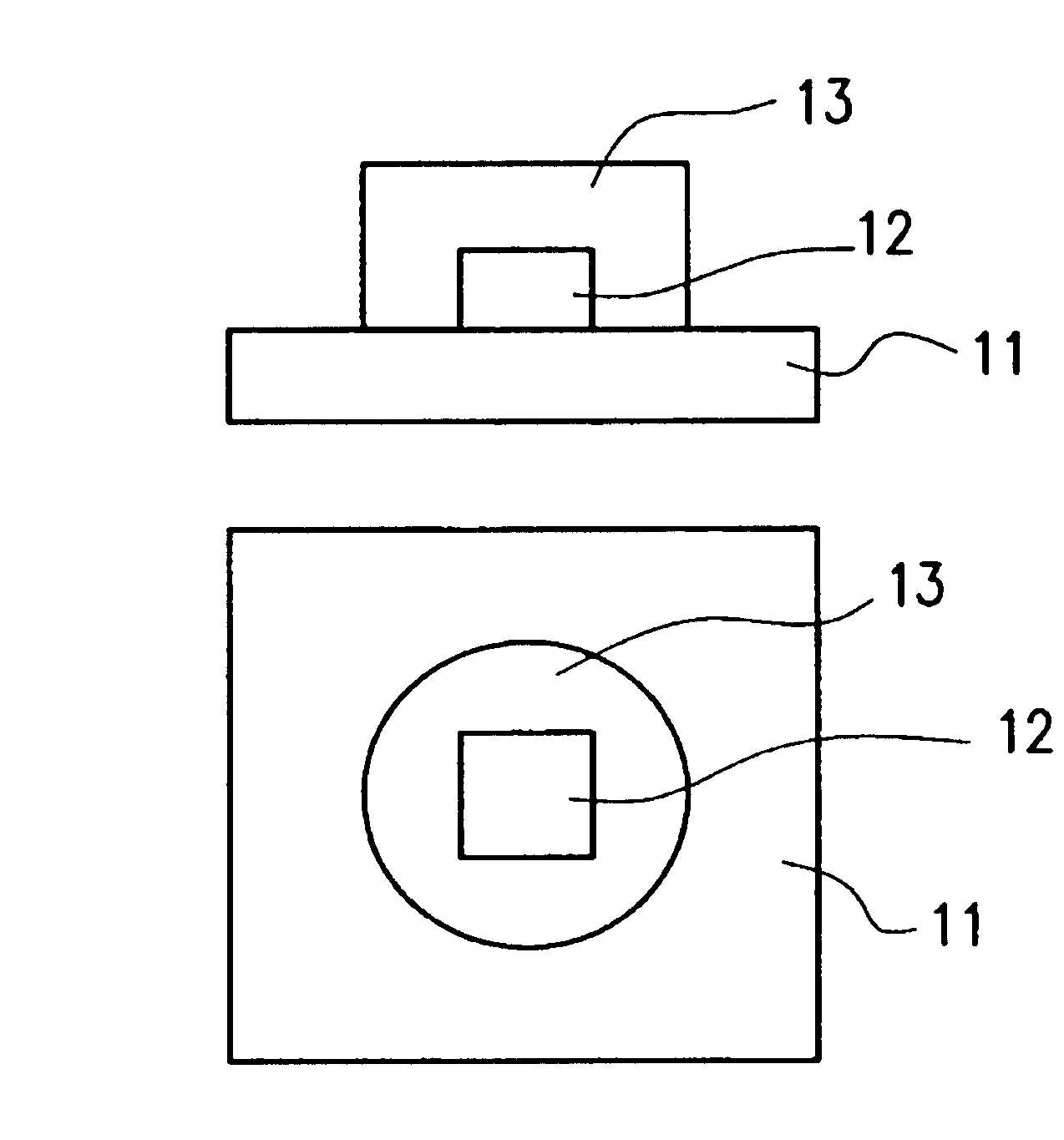
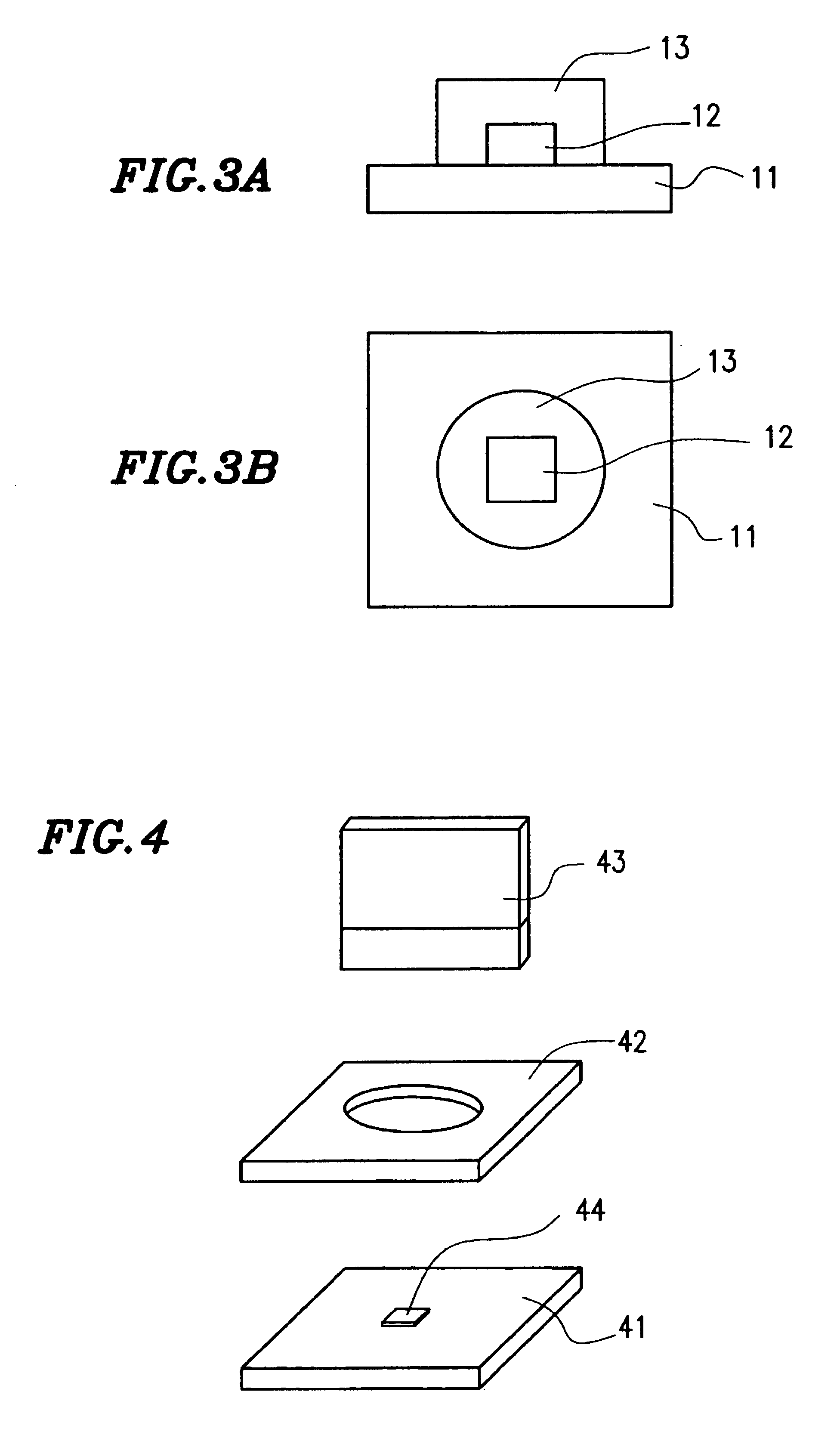
[0077]First, referring to FIGS. 3A and 3B, illustrated is an LED lamp according to a first specific preferred embodiment of the present invention. As shown in FIGS. 3A and 3B, the LED lamp preferably includes a substrate 11, an LED chip 12 bonded to the substrate 11, and a resin portion 13 including a phosphor (or luminophore). In this preferred embodiment, the LED chip 12 is preferably flip-chip bonded to the principal surface of the substrate 11. Although not shown in FIG. 3A or 3B, interconnects are actually provided on the substrate 11 and electrically connected to the electrodes of the LED chip 12 mounted. The LED chip 12 is preferably supplied with a predetermined current or voltage from a lighting circuit (not shown) and through the interconnects on the substrate 11 to make the LED chip 12 emit the light.
[0078]The phosphor dispersed in the resin portion 13 absorbs, and is excited by, the emission of the LED chip 12, thereby producing fluorescence. The light produced from the ...
embodiment 2
[0108]Hereinafter, an LED lamp according to a second specific preferred embodiment of the present invention will be described with reference to FIGS. 8A and 8B. FIGS. 8A and 8B are respectively a cross-sectional view and a plan view schematically illustrating the LED lamp of the second preferred embodiment.
[0109]The LED lamp of the second preferred embodiment preferably includes a substrate 11, an LED chip 12 that has been bonded to the substrate 11, a resin portion 13 including a phosphor, and a reflector 51 that has been attached to the substrate 11. All of these members of the LED lamp, except the reflector 51, are the same as the counterparts of the first preferred embodiment described above, and the description thereof will be omitted herein.
[0110]As shown in FIG. 8A, the reflector 51 preferably has a downwardly tapered reflective surface, which is axisymmetric with respect to the center of the LED chip 12. This reflective surface is preferably the side surface of an opening of...
embodiment 3
[0113]Hereinafter, an LED lamp according to a third specific preferred embodiment of the present invention will be described with reference to FIGS. 9A and 9B. FIGS. 9A and 9B are respectively a cross-sectional view and a plan view schematically illustrating the LED lamp of the third preferred embodiment.
[0114]In this preferred embodiment, a second resin portion 61 is preferably further provided over the substrate 11 so as to cover the cylindrical resin portion 13. Also, this second resin portion 61 is preferably shaped so as to function as a lens. Specifically, this second resin portion 61 preferably transforms light rays 62, which have been emitted from the LED chip 12 through upper and side surfaces thereof, into substantially parallel light rays. As a result, the optical output of the LED lamp increases as measured perpendicularly to the principal surface of the substrate.
[0115]The second resin portion 61 of this preferred embodiment is preferably made of an epoxy resin, for exa...
PUM
 Abstract
Description
Claims
Application Information