

Mobile phone antenna
a mobile phone antenna and antenna technology, applied in the direction of resonant antennas, collapsable antennas, antenna earthings, etc., can solve problems such as resonance frequency displacement, and achieve the effect of preventing resonance frequency displacement and broadening bandwidth
- Summary
- Abstract
- Description
- Claims
- Application Information
AI Technical Summary
Benefits of technology
Problems solved by technology
Method used
Image

Examples
first embodiment
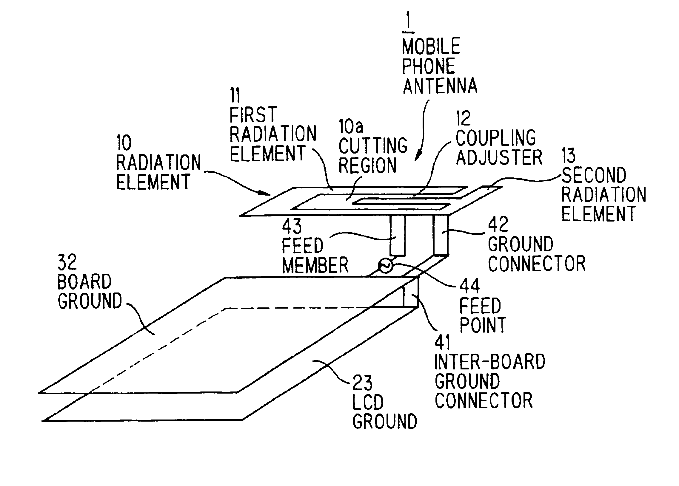
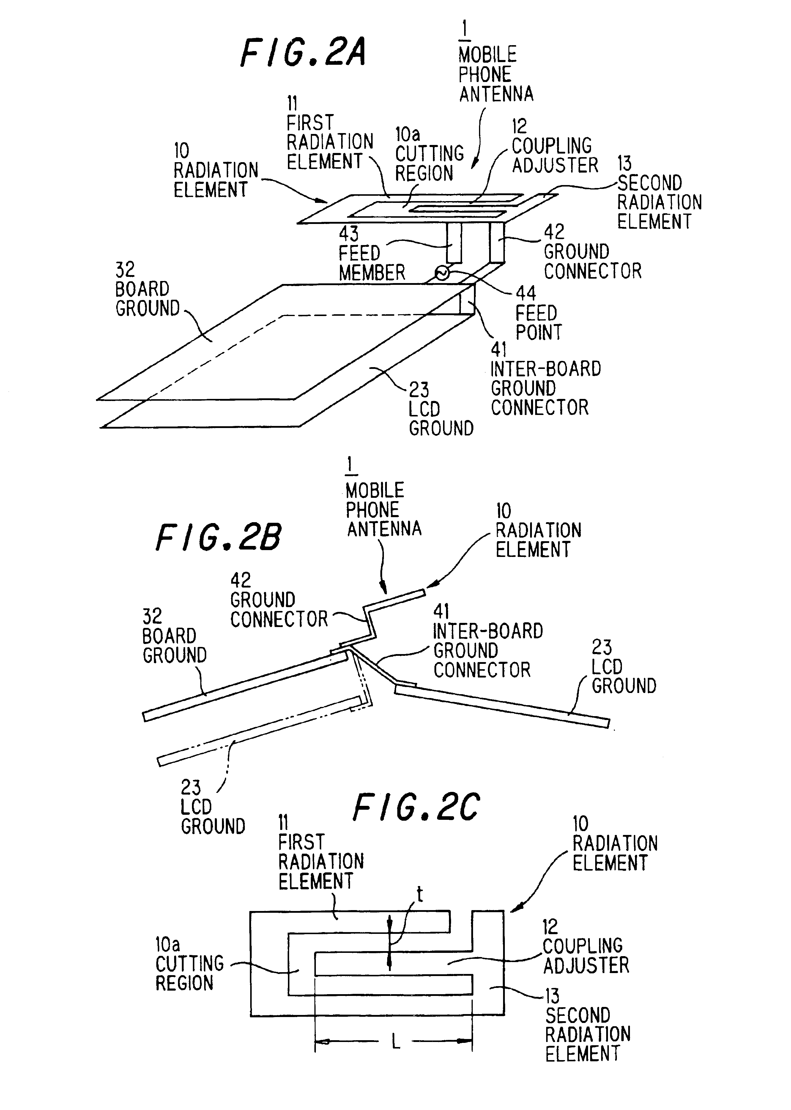
[0038]In the first embodiment, the radiation element 10 is provided with the coupling adjuster 12 and, therefore, the resonance frequency (≈λ / 4) and bandwidth of antenna 1 can be adjusted to a desired value by changing a clearance (t) between the first radiation element 11 and the coupling adjuster 12 and a length (L) of the coupling adjuster 12. Meanwhile, clearance (t) is preferably 2 mm or less. The radiation element 10, ground connector 42 and feed member 43 may be integrally manufactured by punching or etching. Thereby, the number of parts can be reduced.
[0039]FIG. 3 is a side view showing the schematic composition of a folding type mobile phone installing the mobile phone antenna of this embodiment. The folding type mobile phone includes a speaker (not shown), an upper housing 20 on which a liquid crystal display (LCD) is mounted, and a lower housing 30 that has an operation part with numeral keys and cursor keys, a microphone, earphone jack, charging terminal etc. The upper h...
second embodiment
[0048]In the mobile phone antenna 1 of the second embodiment, electromagnetic waves can be radiated from the side. Also, it can be multiband and miniaturized while offering a broadened band, and it can prevent displacement in resonance frequency due to opening and closing of the housing.
[0049]FIG. 6 is a graph showing return loss comparison between the mobile phone antenna of the third embodiment and a comparative example (conventional inverted F dual antenna in FIG. 1). In FIG. 6, A represents characteristics of the comparative example, B represents characteristics of the mobile phone antenna of the third embodiment in the opened state of folding type mobile phone, and C represents characteristics of the mobile phone antenna of the third embodiment in the closed state of folding type mobile phone.
[0050]Table 1 shows specific bandwidth comparison in VSWR=3. In Table 1, GSM stands for global system for mobile communication system and 800 MHz band (870 to 960 MHz) is used in GSM band....
third embodiment
[0052]As shown in FIG. 6 and Table 1, the mobile antenna (B, C) of the third embodiment is enhanced by about 3% in specific bandwidth at GSM band and by about 10 to 23% in specific bandwidth at DCS band as compared to that of the conventional inverted F dual antenna (A). Also, there occurs little displacement in resonance frequency due to opening and closing of the hosing of mobile phone.
[0053]As described above, the mobile phone antenna of the third embodiment can offer a broadened band both at GSM and DCS band and prevent displacement in resonance frequency due to opening and closing of the housing even when it is installed in a mobile phone.
[0054]FIG. 7 is a perspective view showing a radiation element in the fourth preferred embodiment according to the invention. In the fourth embodiment, it is intended to prevent displacement in resonance frequency both at GSM band and DCS band. Thus, there is provided a strip-shaped coupling adjuster 15, on the side face of the radiation eleme...
PUM
 Abstract
Description
Claims
Application Information