Eureka AIR delivers breakthrough ideas for toughest innovation challenges, trusted by R&D personnel around the world.

Magnetic tunneling junction cell array with shared reference layer for MRAM applications

a cell array and reference layer technology, applied in the field of magnetic memories, can solve the problems of interlayer diffusion, degrade or even damage the exchange coupling, and the annealing step may not be able to activate the exchange effect or set the direction of the exchange coupling, so as to improve reliability, reduce cell size, and simplify manufacturing process

Inactive Publication Date: 2005-11-08
APPLIED SPINE TECH
View PDF11 Cites 46 Cited by
  • Summary
  • Abstract
  • Description
  • Claims
  • Application Information

AI Technical Summary

Benefits of technology

"The present invention is about a method and system for creating a magnetic memory. It involves using multiple layers of magnetic elements and reference layers. Each magnetic element has a free layer and a spacer layer, while each reference layer is connected to a corresponding magnetic element. The reference layers are made of a special material called ferromagnetic. A portion of each reference layer acts as a pinned layer and a write line for the corresponding magnetic element. The spacer layer is between the free layer of each magnetic element and the reference layer. This invention has several benefits, including being resistant to processing, having a simplified manufacturing process, smaller cell size, improved reliability, and better stability against stray magnetic field. Additionally, it has improved write efficiency."

Problems solved by technology

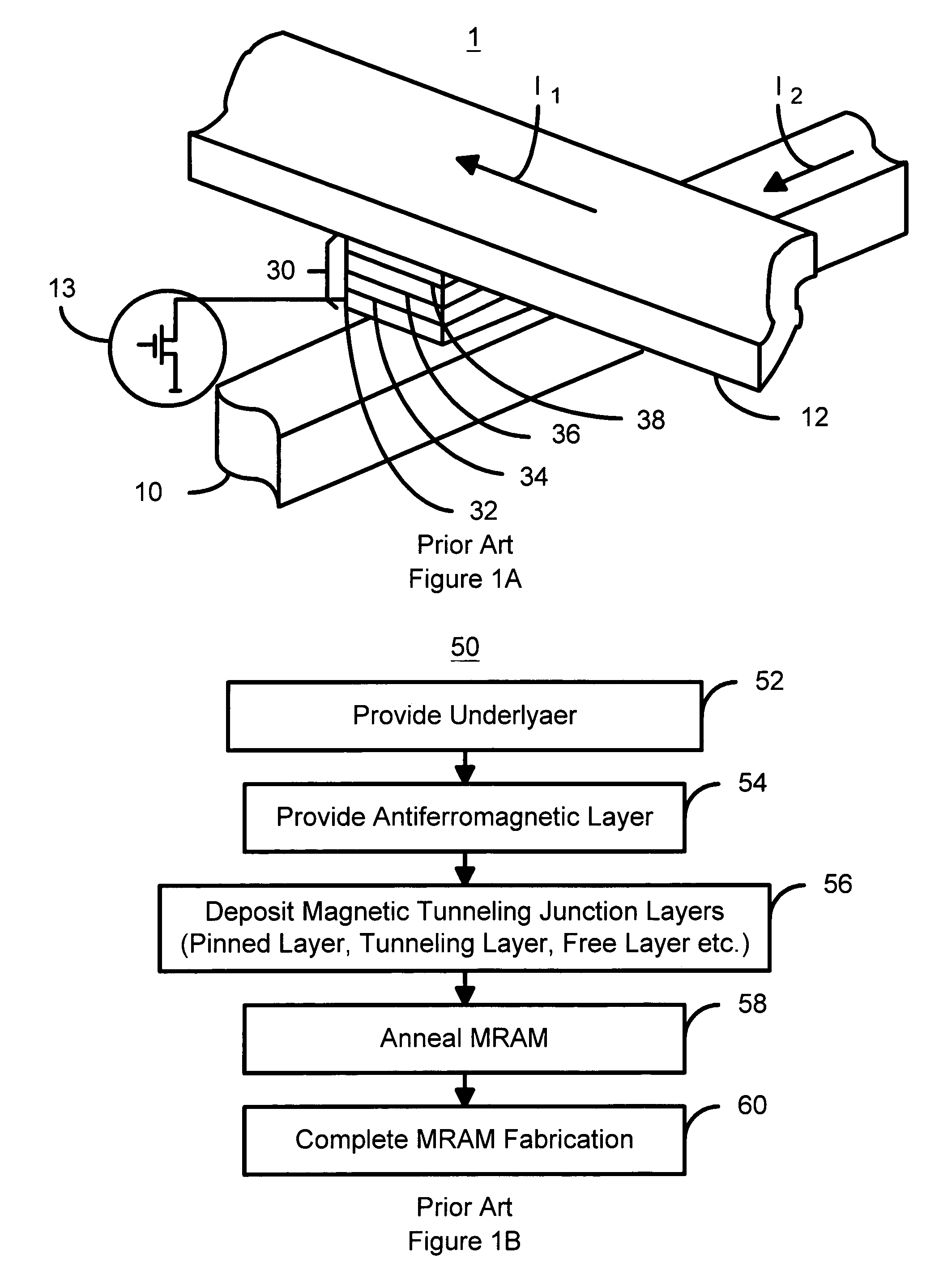
If the temperature used in step 58 is too low, the annealing step may not be able to activate the exchange effect or set the direction of the exchange coupling.
If the temperature used in step 58 is too high, the annealing step may cause interlayer diffusion of different type of materials and degrade or even damage the exchange coupling.

Method used


Image

  • Magnetic tunneling junction cell array with shared reference layer for MRAM applications
  • Magnetic tunneling junction cell array with shared reference layer for MRAM applications
  • Magnetic tunneling junction cell array with shared reference layer for MRAM applications

Examples


first embodiment

[0035]To more particularly illustrate the method and system in accordance with the present invention, refer now to FIG. 3, depicting a three-dimensional view of a magnetic memory 100 in accordance with the present invention. The magnetic memory 100 is preferably an MRAM 100. The MRAM 100 is shown as including three magnetic memory cells 110, 120, and 130 as well as a reference layer 140. The reference layer 140 also acts as a magnetic write line 140. Thus, the magnetic write lines described in the above-identified co-pending application may be used as the reference layer 140. In addition, other magnetic write lines not inconsistent with the present invention as described herein can also be used as the reference layer 140.

[0036]The reference layer 140 includes magnetic vectors 142, 144, 146, 148, and 150 that preferably rotate no more than approximately ninety degrees from their equilibrium position during writing and return to their equilibrium position when writing is completed. Th...

second embodiment

[0047]FIG. 6A depicts a three-dimensional view of a magnetic memory 300, which is preferably an MRAM 300, in accordance the present invention. The MRAM 300 is similar to the MRAM 100 depicted in FIG. 3. Consequently, analogous components of the MRAM 300 are labeled in a manner that is analogous to the MRAM 100. For example, the magnetic memory cells 310, 320 and 330 of the MRAM 300 correspond to the magnetic memory cells 110, 120, and 130 of the MRAM 100. The MTJ stacks 312, 322 and 332 of the MRAM 300 correspond to the MTJ stacks 112, 122, and 132 of the MRAM 100. The free layers 314, 324 and 334 of the MRAM 300 correspond to the free layers 114, 124, and 134 of the MRAM 100. The tunneling layers 316, 326 and 336 of the MRAM 300 correspond to the tunneling layers 116, 126, and 136 of the MRAM 100. The magnetic vectors 318, 328 and 338 of the MRAM 300 correspond to the magnetic vectors 118, 128, and 138 of the MRAM 100. The reference layer 340 corresponds to the reference layer 140....

third embodiment

[0052]FIG. 7 is a three-dimensional view of a magnetic memory 500 that is preferably an MRAM, in accordance the present invention. The MRAM 500 is similar to the MRAM 300 depicted in FIG. 6A. Consequently, analogous components of the MRAM 500 are labeled in a manner that is analogous to the MRAM 300. For example, the magnetic memory cells 510, 520 and 530 of the MRAM 500 correspond to the magnetic memory cells 310, 320, and 330 of the MRAM 300. The MTJ stacks 512, 522 and 532 of the MRAM 500 correspond to the MTJ stacks 312, 322, and 332 of the MRAM 300. The free layers 514, 524 and 534 of the MRAM 500 correspond to the free layers 314, 324, and 334 of the MRAM 300. The tunneling layers 516, 526 and 536 of the MRAM 500 correspond to the tunneling layers 316, 326, and 336 of the MRAM 300. The magnetic vectors 518, 528 and 538 of the MRAM 500 correspond to the magnetic vectors 318, 328, and 338 of the MRAM 300. The layers 517, 527 and 537 of the MRAM 500 correspond to the layers 317, ...


PUM


Abstract

A method and system for providing a magnetic memory is disclosed. The method and system include providing a plurality of magnetic elements and a plurality of reference layers. Each of the magnetic elements includes a free layer and a spacer layer. Each of the reference layers is coupled with a corresponding portion of the magnetic elements. The reference layers are ferromagnetic. A portion of each reference layer functions as at least a portion of a pinned layer for each of the corresponding portion of the magnetic elements. The portion of each of the plurality of reference layers also functions as a write line for the corresponding portion of the plurality of magnetic elements. The spacer layer resides between the free layer of each of the plurality of magnetic elements and the reference layer.

Description

CROSS-REFERENCE TO RELATED APPLICATIONS[0001]This application is claiming under 35 USC 119(e) the benefit of provisional patent application Ser. No. 60 / 454,320 filed Mar. 14, 2003.[0002]The present application is related to co-pending U.S. patent application Ser. No. 10 / 459,133 entitled “MRAM MEMORIES UTILIZING MAGNETIC WRITE LINES”, filed on Jun. 11, 2003, and assigned to the assignee of the present application.FIELD OF THE INVENTION[0003]The present invention pertains to magnetic memories, and more particularly to a method and system for providing write lines for nonvolatile magnetic random access memory (MRAM) that may have a simplified manufacturing process, reduced cell size, improved reliability, improved stability against stray magnetic field, and improved write efficiency.BACKGROUND OF THE INVENTION[0004]Recently, a renewed interest in thin-film magnetic random access memories (MRAM) has been sparked by the potential application of MRAM to both nonvolatile and volatile memor...

Claims


Application Information

Patent Timeline
Patent Type & Authority Patents(United States)
IPC IPC(8): G11C11/15G11C11/02
CPCG11C11/15
Inventor TSANG, DAVID
Owner APPLIED SPINE TECH
Why Eureka
Eureka Blog
Learn More