
Information recording method and optical recording medium therefor

a technology of information recording and optical recording medium, which is applied in the direction of digital signal error detection/correction, thermography, instruments, etc., can solve the problems of incomplete marks, deformation of marks, and low reflectance of marks against laser ligh

Inactive Publication Date: 2005-11-08
RICOH KK
View PDF23 Cites 2 Cited by
  • Summary
  • Abstract
  • Description
  • Claims
  • Application Information

AI Technical Summary

Benefits of technology

[0017]Accordingly, an object of the present invention is to provide an optical recording medium in which information can be repeatedly recorded in a melt-erase mode at a speed four to five times that of the DVD-ROM playback speed (i.e., at a speed of from 14 to 17.5 m / s) and at a recording density equal to or higher than the DVD-ROM recording density.
[0018]Another object of the present invention is to provide an information recording method by which information can be recorded in the optical recording medium at a high speed while the recorded information has good recording properties.

Problems solved by technology

When a pulse having such a waveform is applied to a phase change recording medium, problems such that the resultant recording mark deforms like a tear drop, and marks having a low reflectance against laser light cannot be obtained because the irradiated portion of the recording layer achieves an incomplete amorphous state due to slow cooling speed of the recorded mark.
However, as the recording speed increases, the width of the heating pulse and cooling pulse seriously decreases, and thereby it becomes impossible to heat the recording layer so as to reach the heating temperature (i.e., the amorphous temperature) and the cooling temperature (i.e., the crystal temperature), at which the recording layer can change the phase, resulting in formation of incomplete marks.
Thus, a problem in that the mark does not have a predetermined mark length occurs.
However, when information is repeatedly recorded in a melt-erase mode in the optical recording medium disclosed in ODS 2000 Technical Digest at a speed 4.8 times the DVD speed (i.e., at a speed of 16.8 m / s) using the information recording method disclosed in JP-A 9-134525, the space area of the recording medium does not perfectly achieve a crystallization state (i.e., a part of the space area maintains the amorphous state) because the crystallization speed of the recording medium is not fast enough to match the recording speed, i.e., the recording medium has poor repeat recording properties.
However, the recording properties of the information recorded by the method are inferior to those of the information recorded in a melt-erase mode.

Method used


Image

  • Information recording method and optical recording medium therefor
  • Information recording method and optical recording medium therefor
  • Information recording method and optical recording medium therefor

Examples


example 1

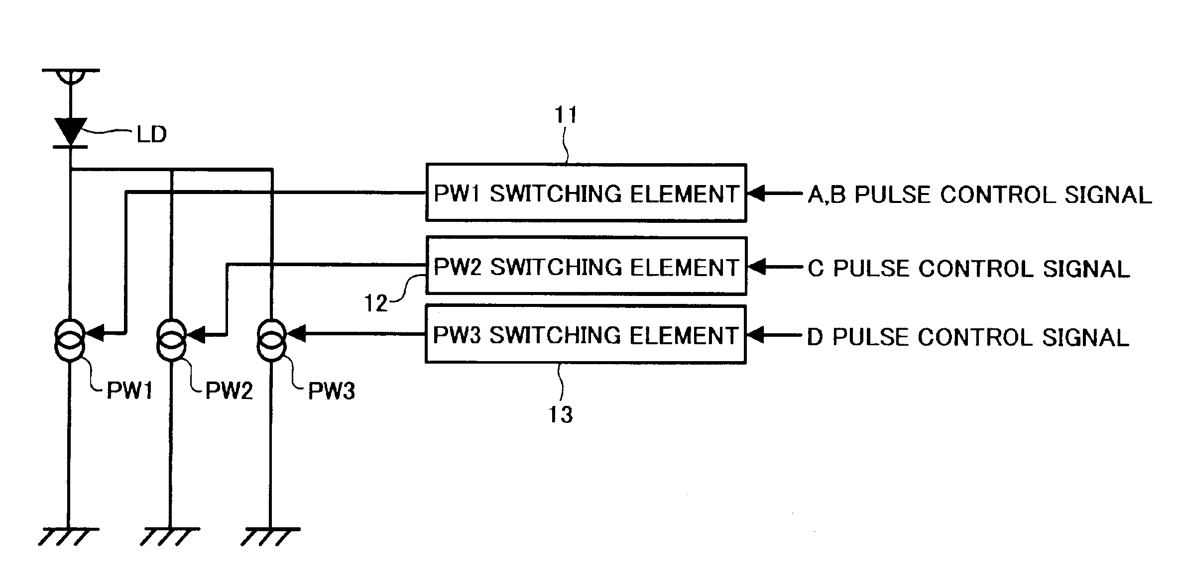
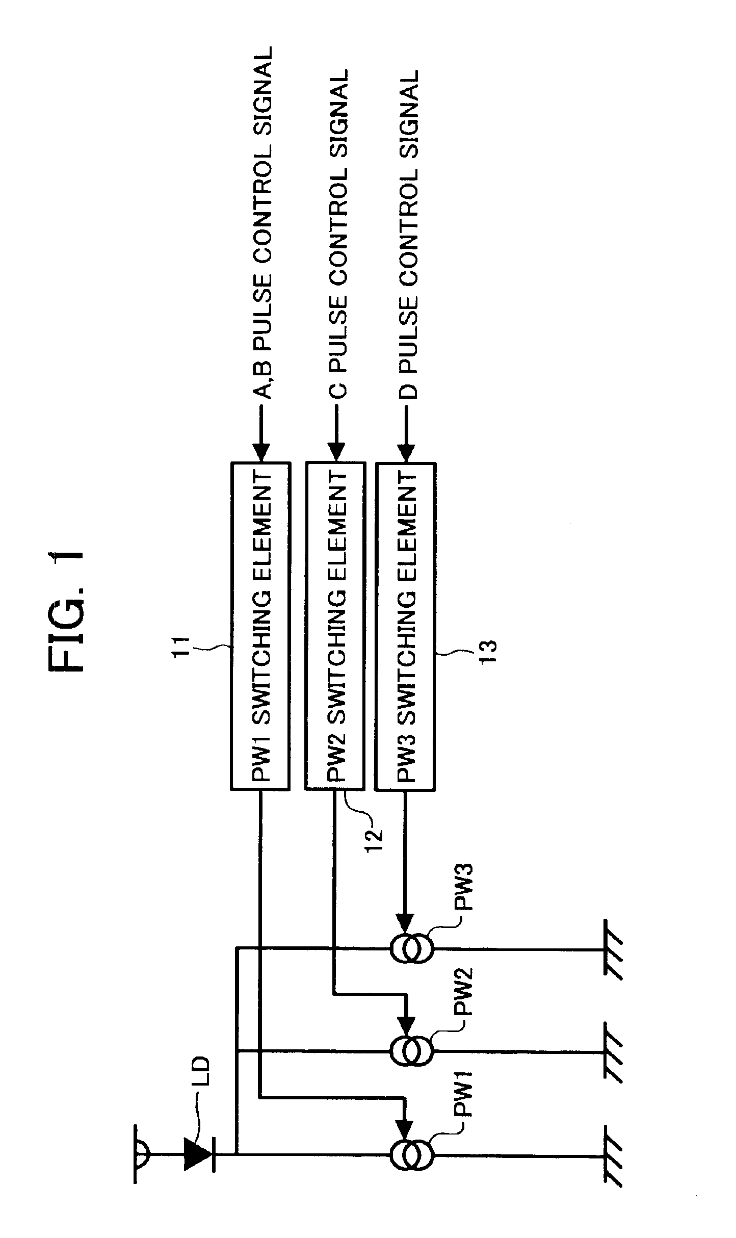
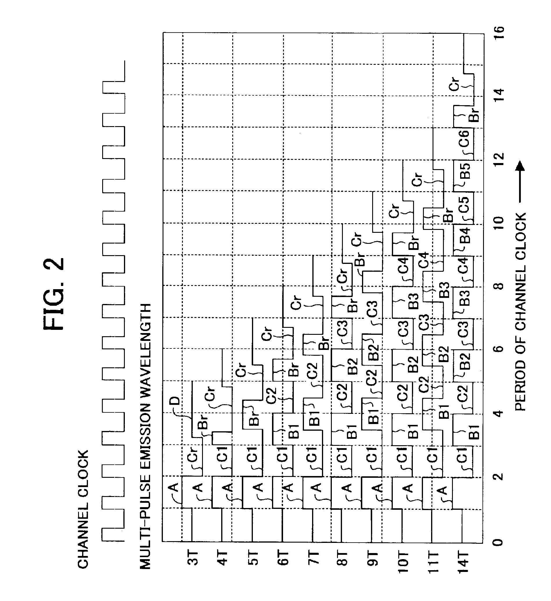
[0102]In the first embodiment of the information record / reproduction apparatus, recording data are recorded in a phase change recording medium while applying laser light having waveform as illustrated in FIGS. 2 and 3. The resultant marks have a predetermined mark length even when the record channel clock is highly frequented.

[0103]When a mark having a shortest mark length of 3T is recorded, multi-pulse laser light constituted of a first heating pulse A having a pulse width of 1.0T, and a last cooling pulse Cr having a pulse width of 1.4T irradiates the optical recording medium.

[0104]When a mark having a mark length of 4T is recorded, multi-pulse laser light constituted of a first heating pulse A having a pulse width of 1.0T, a rear cooling pulse C1 having a pulse width of 1.0T, a last heating pulse Br having a pulse width of 0.5T and a last cooling pulse Cr having a pulse width of 1.3T irradiates the optical recording medium.

[0105]When a mark having a mark length of 5T is recorded,...

example 2

[0129]The procedure for recording and reproduction in Example 1 was repeated except that the wavelength of the last heating pulse Br was changed from 0.4T to 1.0T when marks having a mark length of from 6T to 14T were recorded. The results (σ / Tw) are shown in FIG. 4. As can be understood from FIG. 4, when the pulse width of the last heating pulse Br is from 0.5T to 0.9T, the jitter (σ / Tw) is not greater than 14%. To the contrary, when the last heating pulse Br is less than 0.5T or greater than 0.9T, the rear edges of the resultant marks become unclear, resulting in deterioration of jitter.

[0130]Accordingly, when marks having a mark length of from 6T to 14T are recorded, the pulse width of the last heating pulse Br is set so as to be from 0.5T to 0.9T to form marks having a clear rear edge, resulting in decrease of jitter of reproduction signals.

example 3

[0131]The procedure for recording and reproduction in Example 1 was repeated except that the wavelength of the last cooling pulse Cr was changed from 0.6T to 1.4T when marks having a mark length of from 6T to 14T were recorded. The results (σ / Tw) are shown in FIG. 5. As can be understood from FIG. 5, when the pulse width of the last cooling pulse Cr is from 0.7T to 1.3T, the jitter (σ / Tw) is not greater than 14%. To the contrary, when the last cooling pulse Cr is less than 0.7T or greater than 1.3T, the rear edges of the resultant marks become unclear, resulting in deterioration of jitter.

[0132]Accordingly, when marks having a mark length of from 6T to 14T are recorded, the pulse width of the last cooling pulse Cr is set so as to be from 0.7T to 1.3T to form marks having a clear rear edge, resulting in decrease of jitter of reproduction signals.


PUM

PropertyMeasurementUnit
Temperatureaaaaaaaaaa
Magnetic fieldaaaaaaaaaa

Abstract

An information recording method including irradiating a phase change recording layer of an optical recording medium with either a multi-pulse laser light train having a recording power of Pw or laser light having an erasing power Pe to record a mark having a length nT in the recording layer, wherein n is an integer of from 3 to 14 and T represents a clock cycle, wherein the multi-pulse laser light train has a constitution such that a heating pulse and a cooling pulse are alternated and the number of heating pulses and the number of cooling pulses each increases by 1 when n increases by 2, and wherein when n is from 6 to 14, the last heating pulse and last cooling pulse have a pulse width of from 0.5T to 0.9T and from 0.7T to 1.5T, respectively.

Description

BACKGROUND OF THE INVENTION[0001]1. Field of the Invention[0002]The present invention relates to an information recording method for recording information in a recording medium having a recording layer which can reversibly achieve a crystal phase and an amorphous state by irradiating the recording layer with a multi-pulse laser light train emitted from a light source, and an optical recording medium for the information recording method.[0003]2. Discussion of the Background[0004]Along with the popularization of multimedia, playback-only optical recording media (hereinafter sometimes referred to as media) such as audio CDs and CD-ROMs and information reproduction apparatus have been developed and practically used. Recently, not only recordable optical discs using a dye medium and rewritable magnetooptic discs (MOs) using a magnetooptic medium, but also phase change type media attract attention.[0005]Such phase change type media includes a material having a phase change property of rev...

Claims


Application Information

Patent Timeline
IPC IPC(8): G11B20/14G11B7/00B41M5/26G11B7/0045G11B7/006G11B7/125G11B7/24G11B7/243
CPCG11B7/0062G11B7/243G11B7/258G11B20/1426G11B2007/2431G11B2007/24312G11B2007/24314G11B2007/24316
Inventor OHKURA, HIROKOKAGEYAMA, YOSHIYUKIHARIGAYA, MAKOTOYUZURIHARA, HAJIMEHIBINO, EIKOMIURA, HIROSHIMIZUTANI, MIKU
Owner RICOH KK
Learn More