
Automatic raman gain control

a gain control and automatic technology, applied in the direction of instruments, optical elements, optics, etc., can solve the problems of increasing the cost of equipment and maintenance, reducing the output power per channel at the end of the pumped transmission fiber, and not producing a well-controlled output signal of the raman pumped fiber amplifier with a constant pump level

Active Publication Date: 2005-11-08
LUMENTUM OPERATIONS LLC
View PDF8 Cites 7 Cited by
  • Summary
  • Abstract
  • Description
  • Claims
  • Application Information

AI Technical Summary

Benefits of technology

The present invention provides an optical Raman amplifier that can dynamically control the gain of an amplified signal in an optical communication link. The amplifier has multiple pump sources with different wavelengths that provide optical energy to an optical waveguide. An optical power monitor measures the optical power of the amplified signals and a pump controller compares the optical power to pre-established gain profiles and gain levels of the amplifier in a fully loaded channel configuration. The pump controller modifies the pump power to correspond to changes in channel loading. The invention also provides a method for providing dynamic gain control of an optical Raman amplifier by pre-establishing a set of pump power values and signal level values required to maintain the characterized gain profile and gain levels for a plurality of channel loading configurations. The invention advantageously replaces a costly and complex channel monitor with a single photodiode for providing signal responsive pump control.

Problems solved by technology

A Raman pumped fiber amplifier with a constant pump level will not produce a well-controlled output signal in response to large variations in the input signal level.
When the input power suddenly increases due to the addition of new channels, the Raman pump is depleted, which causes the output power per channel at the end of the pumped transmission fiber to decrease more than desired.
Providing a channel monitor for each Raman stage is quite costly in both equipment and maintenance.

Method used


Image

  • Automatic raman gain control
  • Automatic raman gain control
  • Automatic raman gain control

Examples


Embodiment Construction

[0041]When signal channels are dropped in a Raman amplified link, two effects take place that change the power (gain) levels of the remaining channels: 1) gain saturation of the Raman pumps, and 2) the Raman scattering among signal channels. If the signal output spectrum is somewhat flat when all the signal channels are fully loaded, the dropping of channels will result in higher powers per channel for the remaining channels as well as a negative tilt in the spectrum (ie. higher power at the shorter wavelength end). Adjustment of the powers of the Raman pumps is necessary to offset these changes. In the prior art, this is done in conjunction with a channel monitor which provides full spectral information of the signal channels.

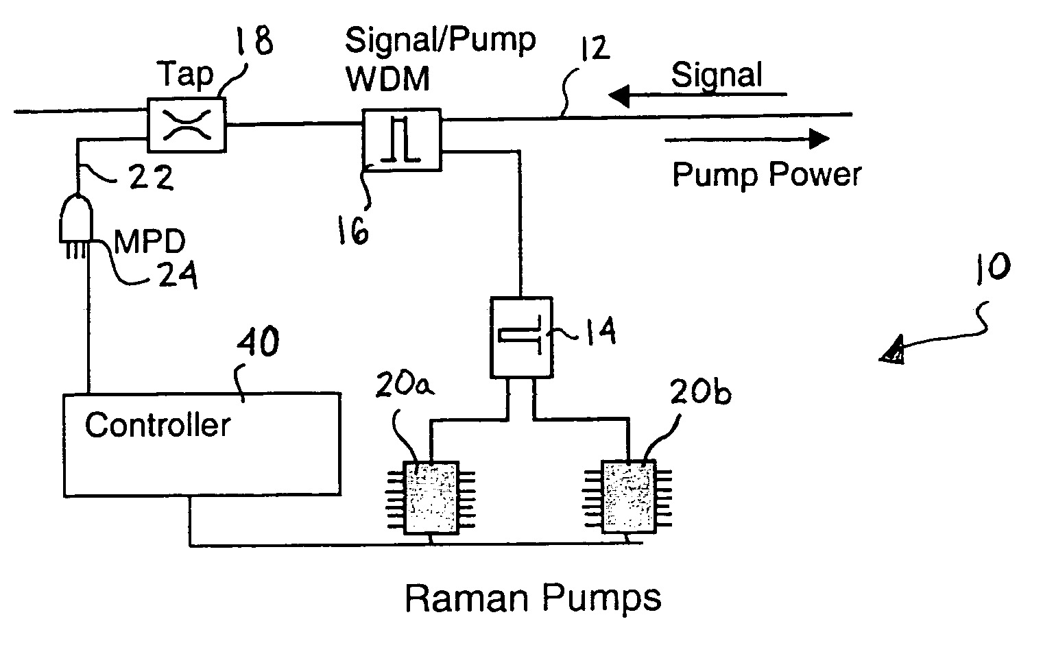
[0042]A distributed Raman amplifier 10 is illustrated in FIG. 1, as an example system. Signal transmission is shown traveling from right to left in the figure on optical fiber 12. Pump power is counter-propagating from left to right from a plurality of pump so...


PUM


Abstract

The invention relates to a method for automatic dynamic gain control in optical Raman amplifiers and an optical Raman amplifier adapted for the same. The present invention has found that in multiple pump Raman amplifiers a substantially linear relationship exists between total amplified signal power and pump power for each of different wavelength pumps, in order to maintain an original gain profile and gain levels for an optical link with a fully loaded channel configuration, in response to dropped channels. In accordance with the method, and an amplifier programmed to practice the method, a set of pump power values and signal level values required to maintain the characterized gain profile and gain levels for a plurality of channel loading configurations are pre-established for the each pump wavelength. A linear function from each set of pre-established values is derived for each pump wavelength. Advantageously, a single photodiode can replace a costly and complex channel monitor for providing signal responsive pump control.

Description

CROSS-REFERENCE TO RELATED APPLICATIONS[0001]This application claims priority from U.S. provisional application No. 60 / 392,298 filed Jul. 1, 2002.MICROFICHE APPENDIX[0002]Not Applicable.TECHNICAL FIELD[0003]The present application relates to a method for automatic dynamic gain control in optical Raman amplifiers and an optical Raman amplifier adapted for the same.BACKGROUND OF THE INVENTION[0004]Optical Raman amplifiers are particularly attractive for use in optical communications networks for their broad wavelength range. In wavelength division multiplexed (WDM) networks, this is particularly important. The Raman gain spectrum is broadened by providing pump energy at a plurality of different wavelengths. In typical Raman amplifiers, channel monitors are provided to monitor the individual channel gain across the transmission spectrum. Information from the channel monitor is provided to a controller to regulate the pump power of the plurality of pump sources at different wavelengths....

Claims


Application Information

Patent Timeline
Patent Type & Authority Patents(United States)
IPC IPC(8): H01S3/30H04B10/17H01S3/13H01S3/131
CPCH01S3/302H04B10/2916H04B10/296H01S3/1305H01S3/1312
Inventor MAO, ERJIMACCORMACK, STUARTROTH, GREGSANDERS, STEVEN
Owner LUMENTUM OPERATIONS LLC
Learn More