
Cutting edge cart

a cutting edge and handling cart technology, applied in the field of bladed devices, can solve the problems of cutting edge wear with usage, permanent wear/damage to the permanent structure of the mold board, particularly earth and/or snow moving equipment, etc., to achieve the effect of reducing the number of parts, easy manufacturing and convenient storag

Inactive Publication Date: 2005-11-15
BLADE ELEVATOR
View PDF4 Cites 3 Cited by
  • Summary
  • Abstract
  • Description
  • Claims
  • Application Information

AI Technical Summary

Benefits of technology

[0005]A further objective is to provide an apparatus that allows a single worker to handle a replacement cutting edge and install / remove the cutting edge to / from a mold board of bladed equipment.
[0006]A yet further objective is to provide an apparatus with a reduced part count that is easily manufactured and easily stored when not in use.
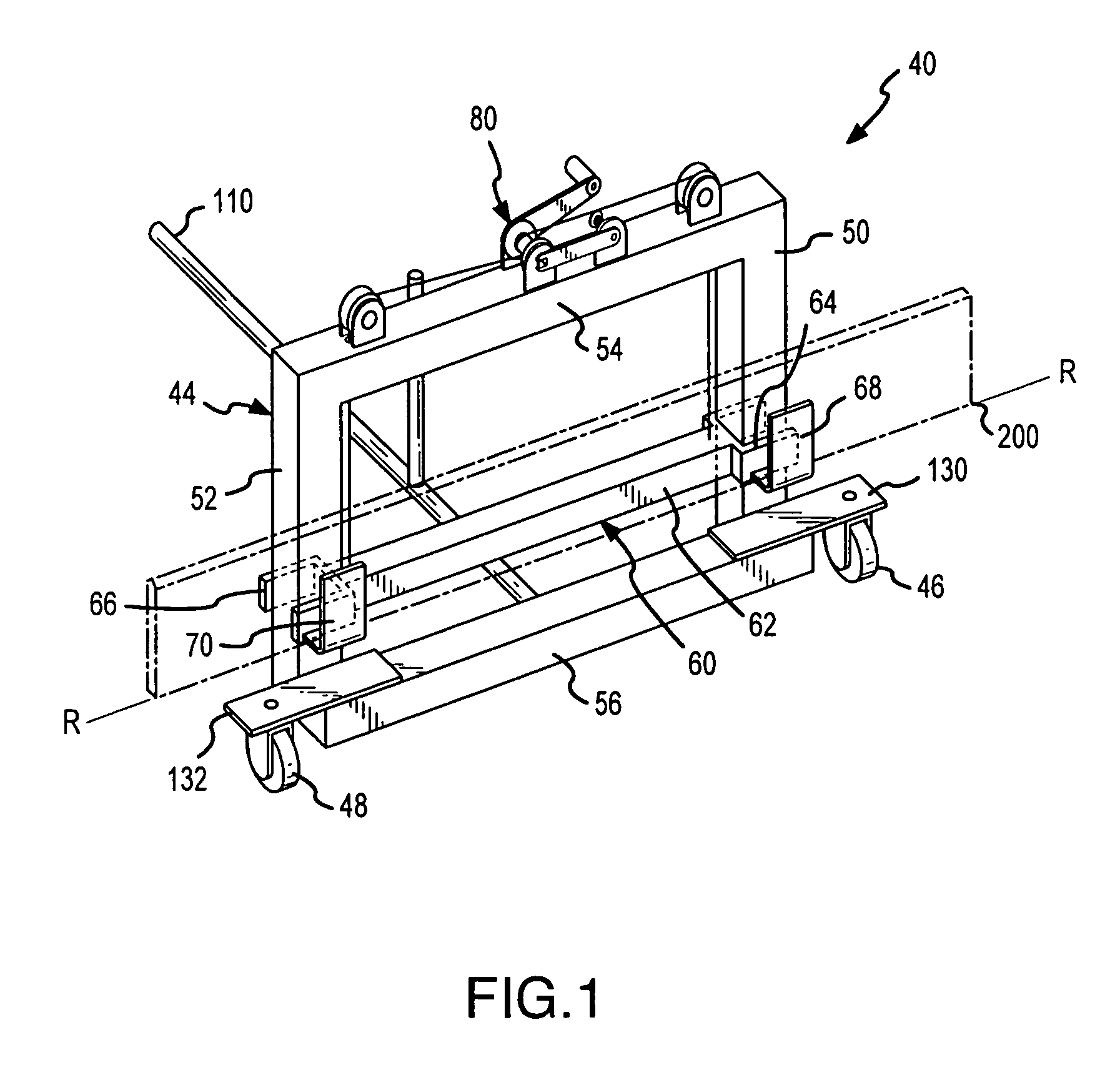
[0008]A blade or cutting edge cart of a first aspect of the present invention includes: a frame; at least one transport member interconnected with the frame to allow the frame to move along a support surface (e.g., to move the cart along the floor of a shop); a carrier assembly that is slidably attached to or interconnected with the frame and that includes an appropriately configured cutting edge support assembly; and an adjuster for selectively moving the carrier assembly relative to the frame. As will be appreciated, movement of the carrier assembly relative to the frame allows a cutting edge being held by the cutting edge support assembly to be raised or lowered to a desired vertical position or elevation relative to the support surface. More particularly, the slidable attachment of the carrier assembly to the frame allows a supported cutting edge to be raised to a vertical position in a near linear fashion and thereby facilitate positioning of the cutting edge relative to the mold board of a road grader or other bladed equipment. That is, the cutting edge may be positioned proximate the mold board and raised to a desired height (e.g., to the height of the mold board). However, this positioning feature may be used for any purpose, such as for removing a cutting edge from a mold board as well.
[0011]As noted, the transport member(s) utilized by the first aspect allow the cart to be moved over a support surface. Any appropriate type of transport member may be utilized, including wheels, rollers, casters, and the like. A single transport member could be utilized (e.g., in the form of a sufficiently long roller). Multiple transport members may also be utilized, preferably spaced along a length dimension of the cutting edge when loaded on the cart. Each transport member may be sized to permit the cart to easily move over the support surface on which the cart is intended to be used. In this regard, the support surface may be a hard smooth surface such as concrete, or, alternatively the support surface may be an uneven earthen surface. In this case, larger wheels may be utilized for a cart intended to be used in the “field” where rough uneven surfaces are expected. Preferably, the transport member(s) utilized by the first aspect will permit the cart to move in any direction. That is, the transport member(s) may be mounted such that they are able to rotate 360° and thereby allow the cart to move in any direction over the support surface.
[0013]The frame utilized by the first aspect may include, for example, a polygonal (i.e., rectangular) structure having upper and lower beams interconnected near the top and bottom ends of first and second side beams. When the frame is in an upright vertical position (e.g., with the first and second side beams being vertically disposed), the above-noted reference plane may be substantially perpendicular to the support surface. In this embodiment, each transport member may be interconnected to the lower beam and the carrier assembly may be slidably attached to the first and second side beams. Further, in this embodiment, the above-noted handle may act as a way to pivot or rotate the frame from a first generally upright position to a second generally horizontal or prone position. In this regard, the handle may act as a lever to pivot or rotate the frame about an axis or pivot (e.g., where at least one, and more preferably where each transport member engages the support surface). Accordingly, the handle may be attached to a lower portion of the frame (e.g., the lower beam) so that it is near the support surface, for example, attached no more than about five or six inches above the support surface, when the frame is in the upright position and perpendicular to the support surface. As will be appreciated, this allows the handle to be near the pivot axis of the cart and therefore provide additional leverage to pivot or rotate the frame between the first and second positions.
[0024]Various refinements exist of the features noted in relation to the subject third aspect of the present invention. Further features may also be incorporated in the subject third aspect of the present invention as well. These refinements and additional features may exist individually or in any combination. The first and second pivoting or rotating the steps of the subject method may generally entail raising and lowering, respectively, a handle that is interconnected to a back surface of the cart. For example, by raising the nonattached, distal end of the handle or moving the same at least generally away from the support surface, the cart may be pivoted or rotated into the above-noted face-down position. Further, this handle may be utilized for directing the cutting edge into the cutting edge supports. That is, while the cart is in the face-down position, the handle may be utilized to direct the frame, carrier assembly and its cutting edge supports (e.g., U-shaped supports) onto a cutting edge that is supported a predetermined distance above the support surface (e.g., ground). The cart may then be pivoted or rotated to the desired upright position by lowering the handle or moving the same at least generally toward the support surface. The cart and supported cutting edge can then be moved along the support surface and relative to the mold board (i.e., pushed or pulled to a desired location over a support surface). Finally, an adjuster may be utilized to move the cutting edge to a desired height relative to the mold board. As will be appreciated, this provides a method for retrieving, transporting, and lifting a cutting edge without having to manually handle that cutting edge.

Problems solved by technology

Though made from durable steel, these cutting edges wear with usage.
Upon reaching a predetermined amount of wear, these cutting edges must be replaced to prevent the bottom edge of the mold board from contacting the ground during use, thus causing permanent wear / damage to the permanent structure of the mold board.
Earth and / or snow moving equipment, and particularly earth and / or snow moving equipment utilized to grade / plow roads (i.e. a “road grader” or “patrol”) are especially susceptible to heavy wear of their cutting edges, as they are often used to move highly abrasive materials such as gravel and asphalt.
As a result, operations that utilize this type of equipment, such as road construction firms and governmental entities that are responsible for maintaining existing roads, spend a considerable amount of time replacing these cutting edges.
The replacement of blade edges is generally time consuming and represents down time for the equipment.
Even though these cutting edges may be separated into several sections, they may still be up to about 12 feet long and, as a metal plate, be quite heavy and awkward to handle.

Method used


Image

  • Cutting edge cart
  • Cutting edge cart
  • Cutting edge cart

Examples


Embodiment Construction

[0039]In the following description, the cutting edge handling cart is set forth primarily in the context of replacing cutting edges bolted to the forward edge of a mold board on a road grader vehicle. However, the present invention is also applicable for replacing the cutting edges on a mold board of a snow plow-type device or any other bladed machinery.

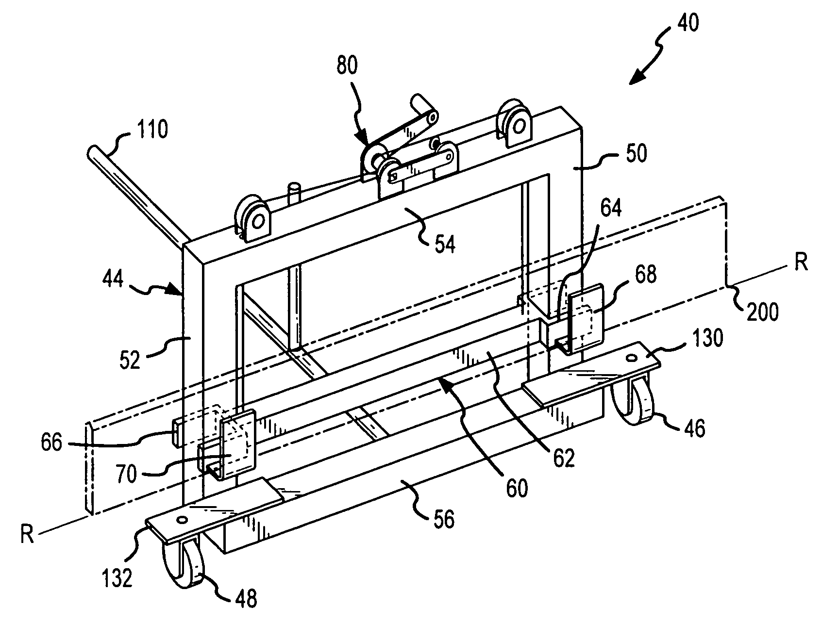
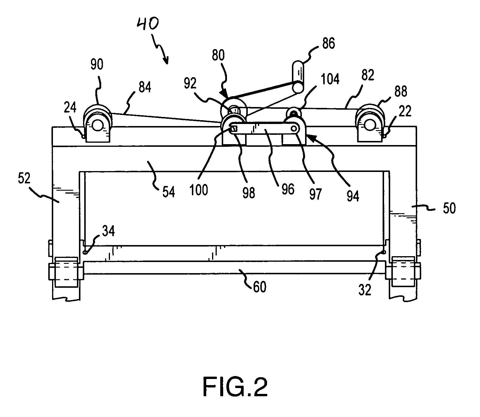
[0040]FIG. 1 is a perspective view of one embodiment of a cutting edge handling cart 40 (hereinafter “cart”). The cart 40 may be utilized to retrieve and transport a cutting edge 200 (shown in phantom in FIG. 1) and position that cutting edge 200 relative to a mold board 210 on a road grader vehicle for attachment thereto (see FIG. 4), as well as to facilitate the removal of such a cutting edge 200 from a mold board 210. The cart 40 generally includes a frame 44, a carrier assembly 60 slidably mounted to the frame 40 so as to move at least generally within a reference plane, cutting edge carriers 68, 70, wheels 46, 48, an adjuster 80...


PUM

PropertyMeasurementUnit
Lengthaaaaaaaaaa
Lengthaaaaaaaaaa
Structureaaaaaaaaaa

Abstract

A cutting edge cart is disclosed that provides an improved means for replacing the replaceable cutting edges on bladed equipment such as road graders and snow plow. The cart allows a single user to retrieve, transport, and position a replacement cutting edge relative to a mold board of the bladed equipment. Generally, the cart contains a frame, two or more transport assemblies attached to the frame, such as wheels, a movable carrier assembly that contains a cutting edge support assembly, and an adjuster. The adjuster is operable to move the carrier assembly between first and second positions relative to the frame allowing the vertical position of a supported cutting edge to be adjusted. The frame and transport assemblies are disposed such that the cart may be rotated or pivoted from a first generally vertical position to a second generally horizontal position. In this horizontal position, a cutting edge may be received within the cutting edge support and the cart rotated back to the generally vertical position.

Description

FIELD OF THE INVENTION[0001]The present invention relates generally to bladed devices such as snow plows and earth working machinery. More particularly, the present invention relates to a blade or cutting edge handling cart for replacing blades / cutting edges that are typically releaseably affixed to bladed devices.BACKGROUND[0002]Earth working and snow removal equipment generally utilize a blade that is contacted with the ground to scrape away or “grade” a desired surface. Generally, the blade can be defined as having two main parts; a long support member, also referred to as a mold board, and a replaceable cutting edge interconnected to and extending downwardly from the lower edge of the support member. The mold board is generally made of steel and is typically concave on its forward side and may be adjustable about a vertical and / or horizontal axis for directing earth / snow removed from a surface. The cutting edge is generally bolted to the lower surface of the mold board and proje...

Claims


Application Information

Patent Timeline
IPC IPC(8): B23Q15/00B62B1/26B62B5/06
CPCB62B1/262B62B1/268B62B5/06B62B2203/10Y10T29/49895Y10T29/53091Y10T29/49998Y10T29/53896Y10T29/53961Y10T29/53909Y10T29/49901
Inventor LORENZ, DONALD E.QUAM, DONALD W.
Owner BLADE ELEVATOR
Learn More