Method and apparatus for high throughput charge injection

a charge injection and high throughput technology, applied in the direction of gasless spraying, lighting and heating apparatus, combustion types, etc., can solve the problem of large potential differences in methods, and achieve the effect of improving the operation of the devi

Inactive Publication Date: 2005-11-15
CHARGED INJECTION TECH
View PDF14 Cites 12 Cited by
  • Summary
  • Abstract
  • Description
  • Claims
  • Application Information

AI Technical Summary

Benefits of technology

[0010]The charge injection device may comprise an electrode, electron gun, electron beam generator, or other such device. The charge injection device may comprise an electrode mounted within the body so that an end surface of the electrode is disposed adjacent the orifices. The end surface of the charge injection device may comprise an edge disposed in alignment with the orifices. The edge, in certain preferred embodiments, comprises a plurality of projections having ends facing the orifices. Without being limited to a theory of operation, it is believed that the end surface of the charge injection device near the central axis should be further away from the body of the device than the edge, which is in alignment with the orifices. It is believed that net charge from the end surface of the charge injection device near the central axis has a greater tendency to be conducted away from the fluent material through the body of the device than the edge in alignment with the orifices. It has been found that a concave end surface on the charge injection device improves operation of the apparatus. It has also been found that providing a plurality of projections at the edge of the charge injection device, also improves the operation of the apparatus.
[0014]The body of the apparatus may comprise a forward wall and the orifices may be formed in the forward wall. In certain preferred embodiments, the forward wall includes a recess disposed on the central axis, between the orifices, on an interior side of the body. In certain preferred embodiments, the interior side of the forward wall in-between the orifices comprises a dielectric material. Without being limited to a theory of operation, it is believed that a conductive surface located between orifices, on an interior side of the forward wall, may decrease the effectiveness of the apparatus. It is believed that net charge imparted to the fluent material may be conducted away from the fluent material through the surface on the interior side of the forward wall. It has been found that providing a recess or a dielectric material at this location improves the functioning of the apparatus.
[0023]In a preferred embodiment, the orifices include at least one first orifice closer to the charge injection device than at least one second orifice and the net charge is varied so that the fluent material issuing from the at least one second orifice is dispersed. Without being restricted to any theory of operation, it is believed that an orifice located further away from the charge injection device than other orifices will issue fluent material somewhat less disbursed than the other orifices. However, by varying the net charge imparted to the fluent material flowing to the orifice located further away from the charge injection device will improve operation of the device.

Problems solved by technology

These methods require large potential differences developed over the large air gap between the orifice and the charged remote surface.

Method used


Image

  • Method and apparatus for high throughput charge injection
  • Method and apparatus for high throughput charge injection
  • Method and apparatus for high throughput charge injection

Examples


Embodiment Construction

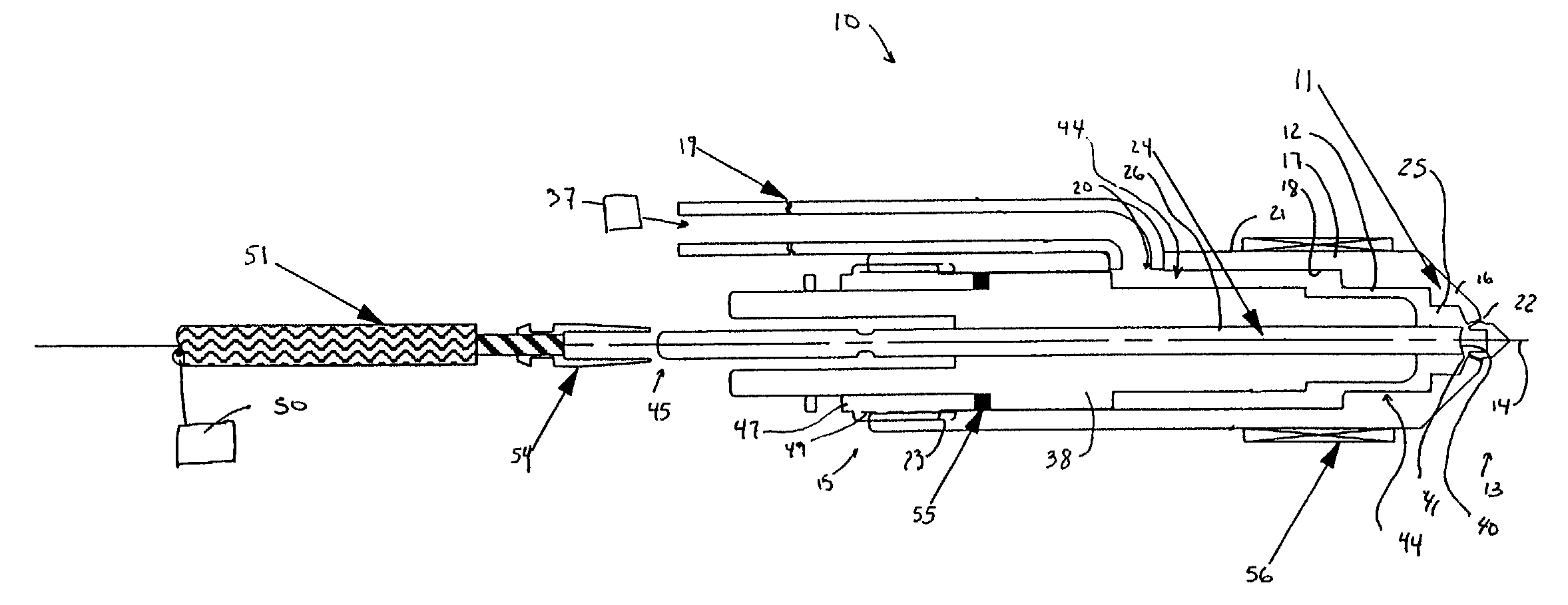
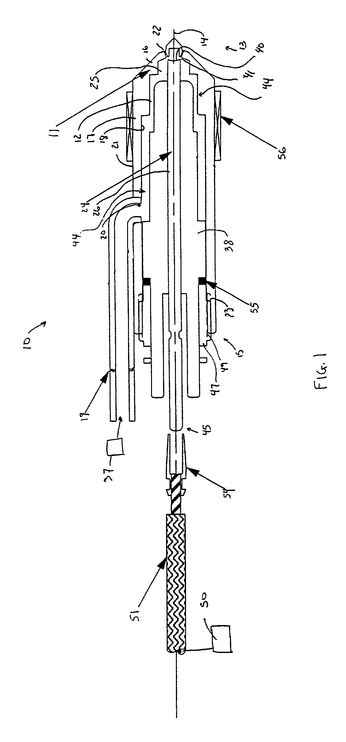
[0039]An embodiment of the invention is shown in FIGS. 1–5. A dispersing apparatus 10 comprises a body 11 having a central axis 14. The body 11 may comprise an electrically conductive body, such as a metallic body 11. The body 11 may also comprise a ceramic or plastic body 11.

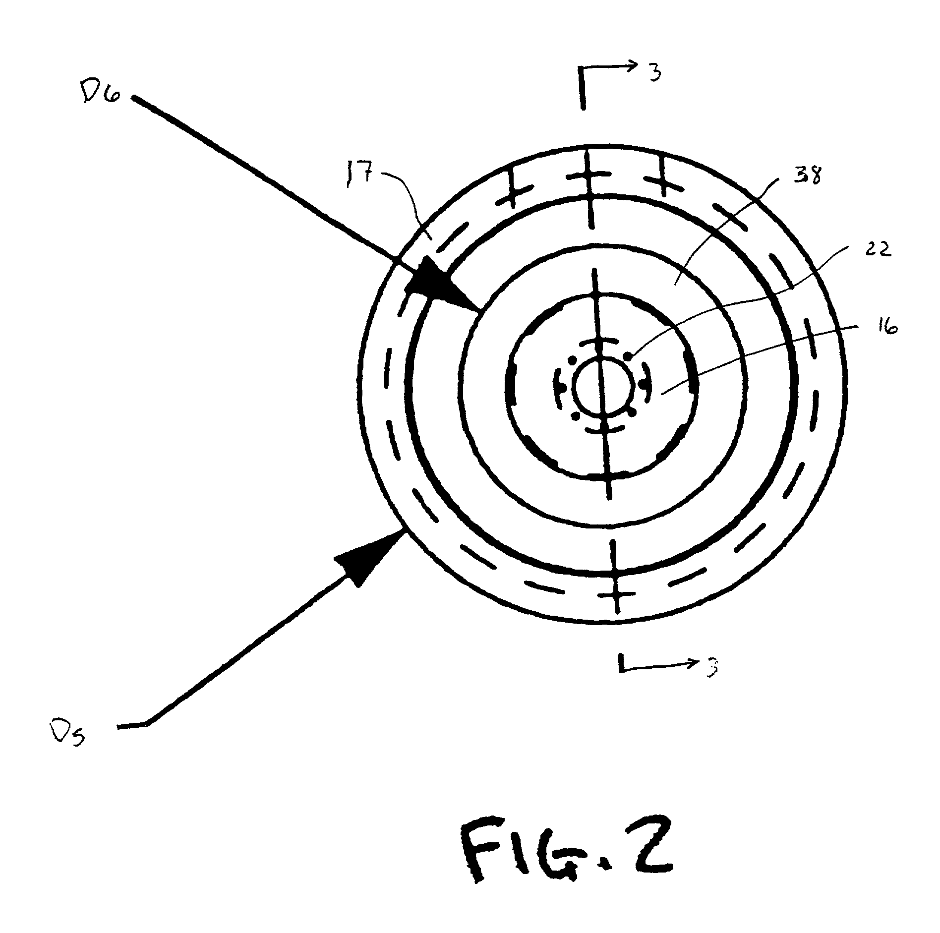
[0040]A liquid supply line 19 is attached to the body 10 at an aperture 20 in the body 11. The body 11 is generally cylindrical and formed by a wall 17 with an interior surface 18 and an exterior surface 21. The body 11 shown in FIG. 1 has a generally cylindrical shape, but a dispersing apparatus 10 in accordance with embodiments of the invention may have various shapes. The shape of the body 11 is not essential.

[0041]The body 11 defines a first end 13 and a second end 15, opposite from first end 13. The wall 17 tapers towards the first end 13 to a generally conical forward wall 16 at the first end 13 of the apparatus. The forward wall 16 has at least two orifices formed therein. For example, in the embodiment ...


PUM


Abstract

An apparatus for dispersing fluent material comprises a body defining a plurality of orifices arranged around a central axis and a charge injection device arranged on the central axis.

Description

STATEMENT REGARDING FEDERALLY SPONSORED RESEARCH OR DEVELOPMENT[0001]This invention was made with government support and the government has certain rights in the invention.FIELD OF THE INVENTION[0002]The present invention relates to electrostatic methods for dispersing fluent material and to apparatus for dispersing fluent materials.BACKGROUND OF THE INVENTION[0003]Electrostatic methods may be utilized in many applications, such as combustion of fuels and manufacture of fibrous materials.[0004]Certain methods of electrostatic atomization of liquids are known. These methods use an electrode defining an orifice. The liquid is passed through the orifice, from a first side of the electrode to a second side. An oppositely charged surface is remotely disposed with respect to the electrode, on the second side of the electrode. These methods require large potential differences developed over the large air gap between the orifice and the charged remote surface. The electric field developed o...

Claims


Application Information

Patent Timeline
Patent Type & Authority Patents(United States)
IPC IPC(8): B05B5/025B05B5/053B05B5/035F23D11/38F23D11/00F23D11/36F23D11/32B05B1/14
CPCB05B5/035B05B5/0533F23D11/32F23D11/38B05B1/14
Inventor KELLY, ARNOLD J.
Owner CHARGED INJECTION TECH
Why Eureka
Try Eureka