Shock absorbing apparatus

Inactive Publication Date: 2005-11-15
BERGEY KARL H
View PDF7 Cites 29 Cited by
  • Summary
  • Abstract
  • Description
  • Claims
  • Application Information

AI Technical Summary

Benefits of technology

[0009]The present invention achieves its intended purposes, objects, and advantages through a new, useful, and unobvious combination of component elements, with the use of a minimum number of functioning parts, at a reasonable cost to manufacture, and by employing only readily available materials. In these respects, the present version of the invention substantially departs from the conventional concepts and designs of the prior art, and in so doing provides an apparatus that substantially fulfills this need. Additionally, the prior patents and commercial techniques do not suggest the present inventive combin

Problems solved by technology

Additionally, the prior patents and commercial techniques do not suggest the present i

Method used


Image

  • Shock absorbing apparatus
  • Shock absorbing apparatus
  • Shock absorbing apparatus

Examples


Embodiment Construction

[0025]The following detailed description is of the best currently contemplated modes of carrying out the invention. The description is not to be taken in a limiting sense, but is made merely for the purpose of illustrating the general principles of the invention, since the scope of the invention is best defined by the appended claims.

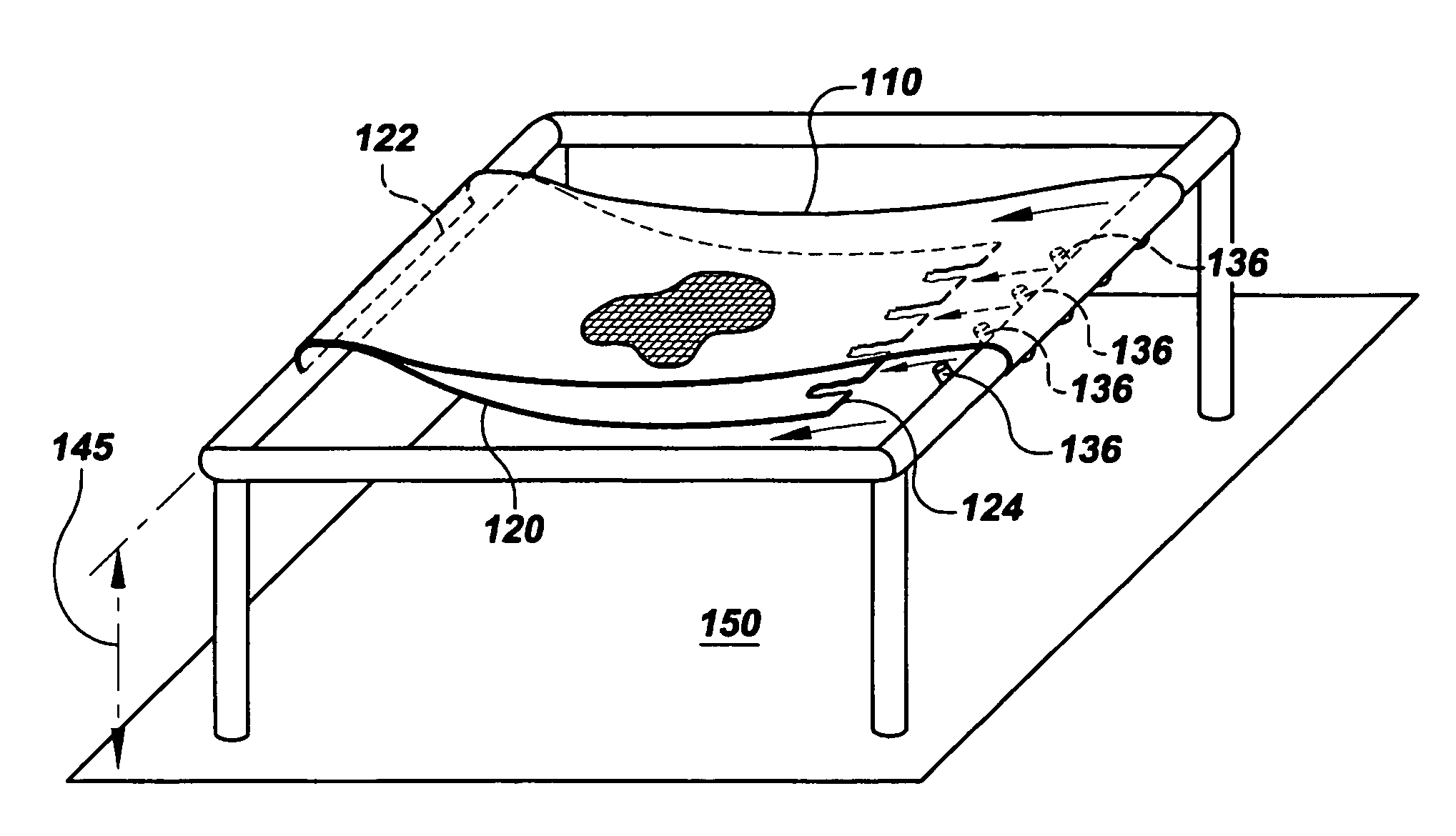
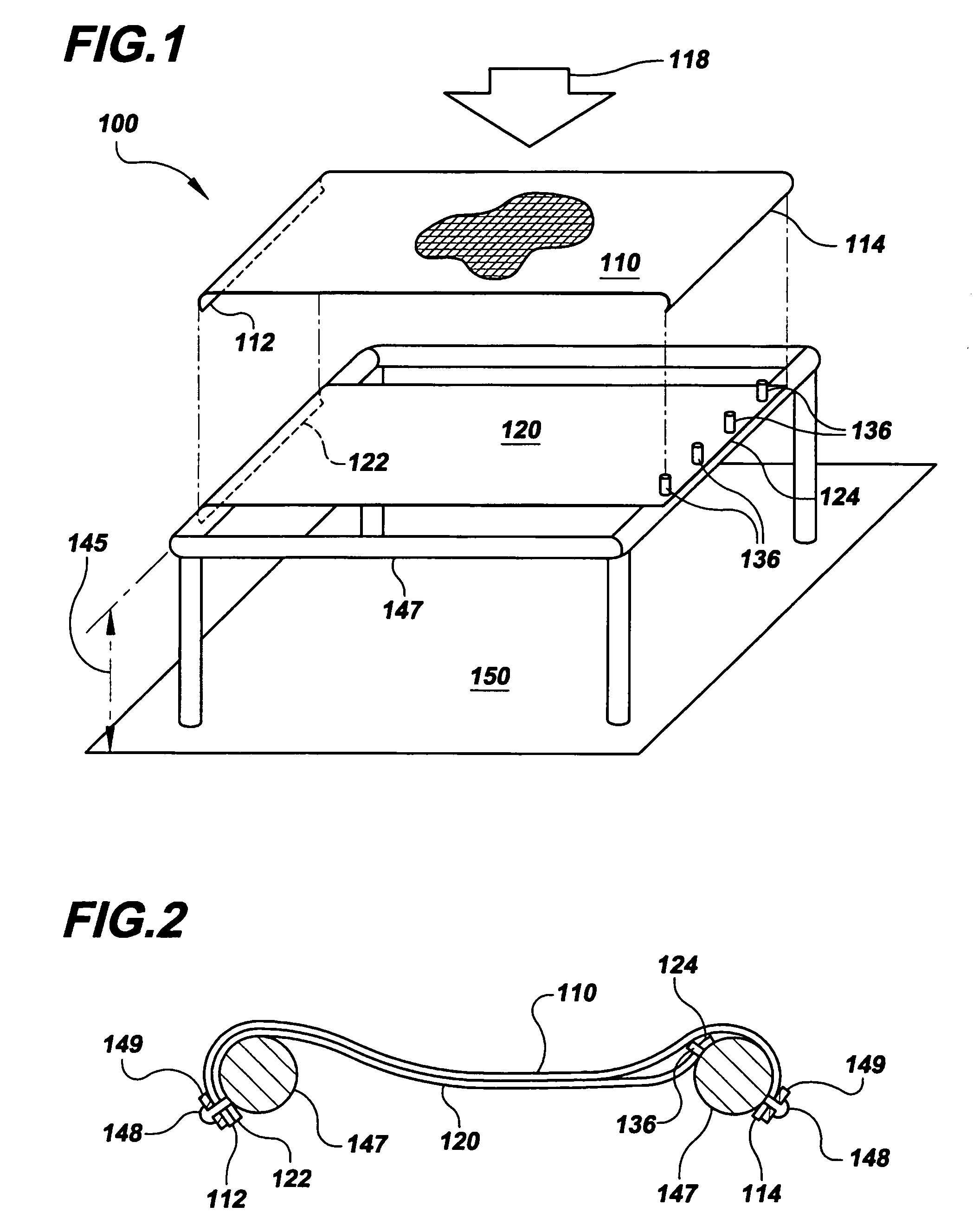
[0026]Referring now to FIG. 1, which shows an exploded view of an embodiment 100 of the invention, the general principles of the invention may be seen as implemented as a portion of a seating apparatus. The seating apparatus 100 is shown as a frame 147 supporting a first metal sheet 110 and a second metal sheet 120, with the first metal sheet 110 shown in an exploded view for clarity. Both metal sheets 110, 120 may be supported by the frame 147 a spaced distance 145 from a basal surface 150. The basal surface 150 may be considered to be any surface that might cause harm, injury, or damage to an object residing on the surface of the first metal sheet 110...


PUM


Abstract

An energy-absorbing structure is provided, which comprises two generally parallel metal sheets arranged to receive an impacting force against the uppermost sheet and cooperatively prevent an object supported by the uppermost sheet from impacting a basal surface. One metal sheet may be fabricated from expanded metal for its non-isotropic shock-absorbing properties. The other metal sheet may be fabricated from a non-elastic material and arranged to be supported by pins inserted through holes along the perimeter of the sheet, so that when an impacting force is applied, it will resist the force until the force is sufficiently strong so as to shear the pins through the sheet and abruptly release, thus allowing the metal sheet fabricated from expanded metal to absorb the remainder of the impacting force. The invention may find application in vehicles operating in the air, land, or sea.

Description

BACKGROUND OF THE INVENTION[0001]The present invention relates generally to shock-absorbing structures, more particularly, to safety features incorporated into vehicle seats such as those found in aircraft, to protect the occupant, insofar as it is possible, from shock induced injury. Such structures may find utility in related fields such as automotive, machinery, or any vehicle having human occupants.[0002]Vehicles are generally operated by human operators in a seated position within the vehicle. Such vehicles include land based vehicles such as automobiles, trucks, earth moving equipment, and the like; sea based vehicles such as boats and submarines; and flying vehicles such as aircraft, helicopters, and spacecraft. Because the vehicle is generally in motion, external forces may cause the compartment to abruptly change its direction of motion, resulting in forces exerted upon the occupant. These forces are made up of a horizontally oriented component and a vertically oriented com...

Claims


Application Information

Patent Timeline
IPC IPC(8): B60N2/42B60N2/427
CPCB60N2/4242B60N2/42709
Inventor BERGEY, KARL H.
Owner BERGEY KARL H
Why Eureka
Try Eureka