Method and apparatus for three dimensional imaging using infrared radiation

a three-dimensional imaging and infrared radiation technology, applied in the field of three-dimensional (3d) tomography, can solve the problems of inability to directly integrate cone beam data with image reconstruction, inability to acquire 3d data sets a 2d slice at a time, and inability to achieve accurate and accurate image reconstruction results. , the effect of large and expensive cos

Inactive Publication Date: 2005-11-15
PURDUE PHARMA LP
View PDF10 Cites 11 Cited by
  • Summary
  • Abstract
  • Description
  • Claims
  • Application Information

AI Technical Summary

Benefits of technology

[0022]The relative scanning angle (relation of the scanning elements to the object) is then changed to effect scanning from a different angle and another spectral data block is obtained. The scanning angle is changed at predetermined angular increments until a complete 360 degree view is obtained for the desired spectral range at each angular incremental position.

Problems solved by technology

Acquiring a 3D data set a 2D slice at a time is inherently tedious and time-consuming.
The cone beam data, however, are not directly compatible with image reconstruction through inverse Radon transformation, which requires the use of planar integrals of the object as input.
Photomultiplier tubes are quite sensitive, but are relatively large and expensive.

Method used


Image

  • Method and apparatus for three dimensional imaging using infrared radiation
  • Method and apparatus for three dimensional imaging using infrared radiation
  • Method and apparatus for three dimensional imaging using infrared radiation

Examples


Embodiment Construction

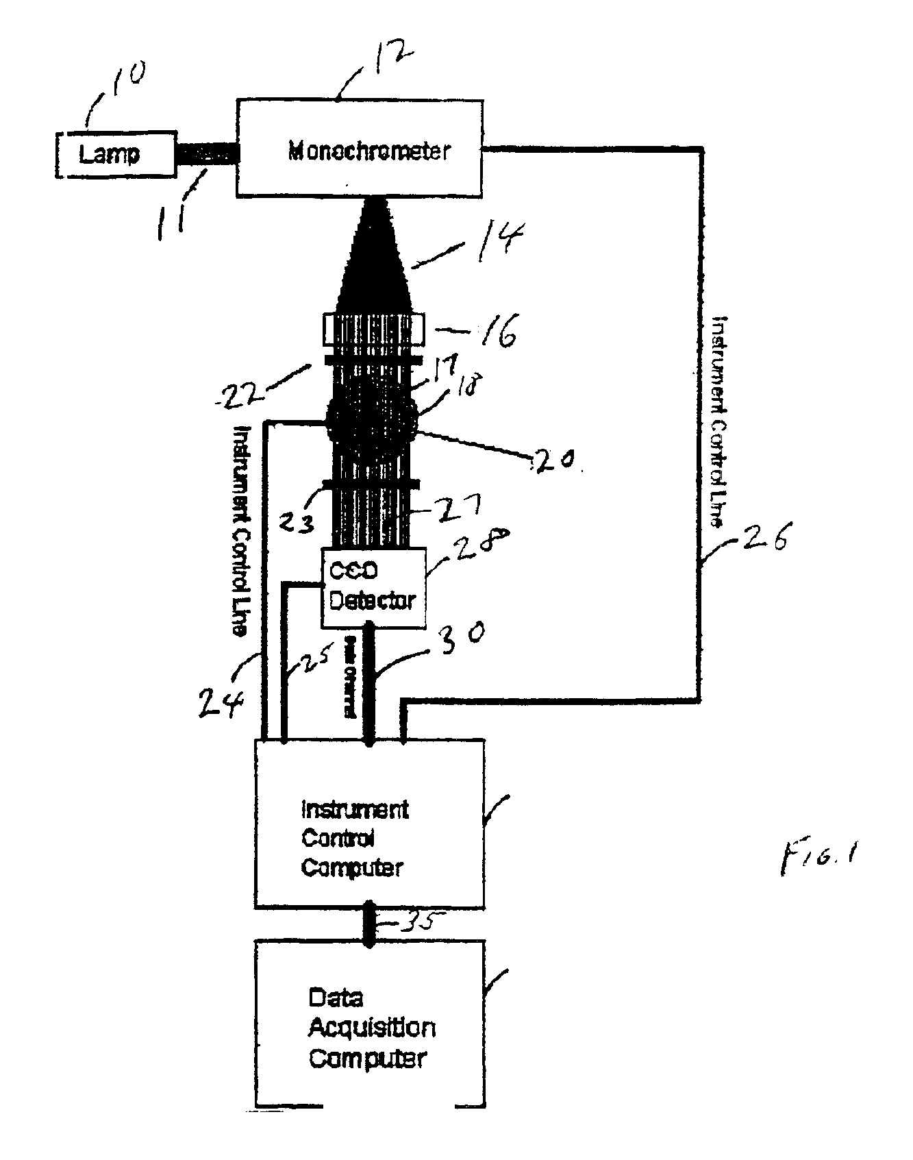
[0033]Referring to FIG. 1, there is shown an exemplary infrared tomography system according to the present invention. Preferably, the system is automated by a computer program residing on the control computer 32 operably connected to each component in the system by instrument control lines 24, 25 and 26. The control lines 24, 25 and 26 are constructed and arranged to allow for the exchange of digital information between the computer 32 and the system components to effect operation in a prescribed sequence at the direction of the program, and to transfer digital imaging information to the control computer 32 for storage on the data acquisition computer 34.

[0034]A lamp 10 provides a beam of light 11 to a monochrometer 12, which, in turn, projects monochromatic (one wavelength) radiation 14. As already discussed, a wide variety of monochrometers are suitable for generating the monochromatic radiation, including, for example, dispersive-type monochrometers and filter-type monochrometers...


PUM

PropertyMeasurementUnit
wavelengthaaaaaaaaaa

Abstract

An infrared three-dimensional imaging system and method in which an object is irradiated by monochromatic radiation in the near-infrared or mid-infrared region of the spectrum. A spectral image is captured for each wavelength in a spectral range by a radiation detector to create a spectral image data block that is stored on a data storage device. The object is rotated by some predetermined angular increment until a complete three hundred and sixty degree view is obtained so that a spectral image data block is created for each angular position. Each spectral image data block is compressed to its most relevant spectral information and used to re-create a three dimensional image by a known computerized tomography algorithm.

Description

FIELD OF THE INVENTION[0001]The present invention relates generally to three-dimensional (3D) tomography.BACKGROUND OF THE INVENTION[0002]Every type of atom and molecule vibrates at different speeds, giving off light at its own unique set of frequencies. Thus, the chemical composition of an object can be ascertained by studying light that passes through an object. This field of science is known as spectroscopy. The light, when projected on some medium after passing through an object, creates a spectral image. When applied in a two-dimensional world, this technique is known as 2D imaging, or hyper spectral imaging. When spectroscopy and imaging are applied through a three dimensional volume it is known as 3D tomography. This technique is utilized routinely in the medical field in the form of computerized tomography (CT), which uses x-rays to provide a nondestructive or noninvasive method of generating visual sectional views of an object.[0003]In general, a computerized tomography (CT...

Claims


Application Information

Patent Timeline
Patent Type & Authority Patents(United States)
IPC IPC(8): G01N21/47G01N21/31G01N21/35
CPCG01N21/4795G01N21/3563G01N21/359
Inventor BYNUM, KEVIN C.KASSIS, ABE S.
Owner PURDUE PHARMA LP
Why Eureka
Try Eureka