Systems and methods for collapsing air lines in nanostructured optical fibers

a nano-structured optical fiber and air line technology, applied in the field of nano-structured optical fibers, can solve the problems of the critical angle of reflection angle of light rays within the fiber, the angle of macrobending loss, and the extrinsic loss of the fiber

Inactive Publication Date: 2009-08-13
CORNING CABLE SYST LLC
View PDF14 Cites 50 Cited by
  • Summary
  • Abstract
  • Description
  • Claims
  • Application Information

AI Technical Summary

Benefits of technology

[0009]A second aspect of the invention is a method of collapsing air lines in a portion of a nanostructure optical fiber that includes an air line region formed within a cladding region. The method includes forming at least first and second laser beams each having a respective, mid-infrared (MIR) wavelength and an optical power that is the same or substantially the same. The method als

Problems solved by technology

Improper handling and deployment of a fiber optic cable can result in macrobending losses, also known as “extrinsic losses.” In ray-optics terms, severe bending of an optical fiber can cause the angles at which the light rays reflect within the fiber to exceed the critical angle of reflection.
While nanostructure fibers offer a significant increased improvement in the minimum bend radius, there are issues with connectorizing such fibers due to the voids present at the end of a cleaved fiber.
One connectorization issue is that contaminants can fill the fiber voids and ingress at the fiber end, which reduces the efficiency of the connection.
Such contaminants include moisture and micro-debris generated at the connector end face during the connector polishing processes, such as mixtures of zirconium ferrule material and silica glass removed during polishing, abrasives from polishing films, and deionized water.
These contaminants may become trapped or embedded in the fiber at the connector end face.
Due to the various forces and the attendant heat the connector end experiences during the polishing proces

Method used


Image

  • Systems and methods for collapsing air lines in nanostructured optical fibers
  • Systems and methods for collapsing air lines in nanostructured optical fibers
  • Systems and methods for collapsing air lines in nanostructured optical fibers

Examples


Embodiment Construction

[0032]Reference is now made in detail to the present preferred embodiments of the invention, examples of which are illustrated in the accompanying drawings. Whenever possible, the same reference numbers and symbols are used throughout the drawings to refer to the same or like parts.

Nanostructure Optical Fibers

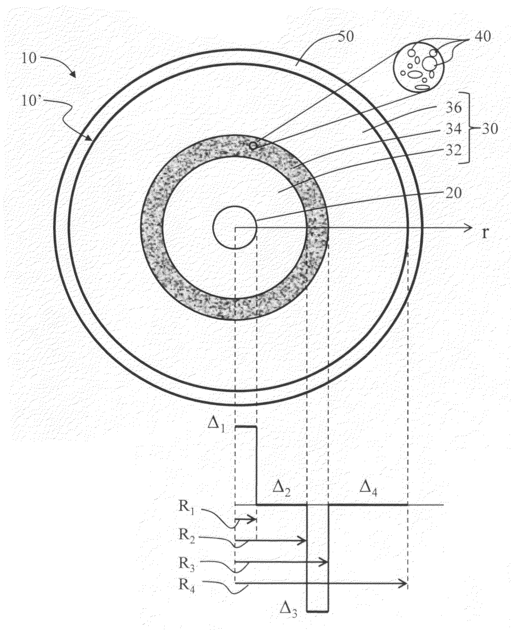
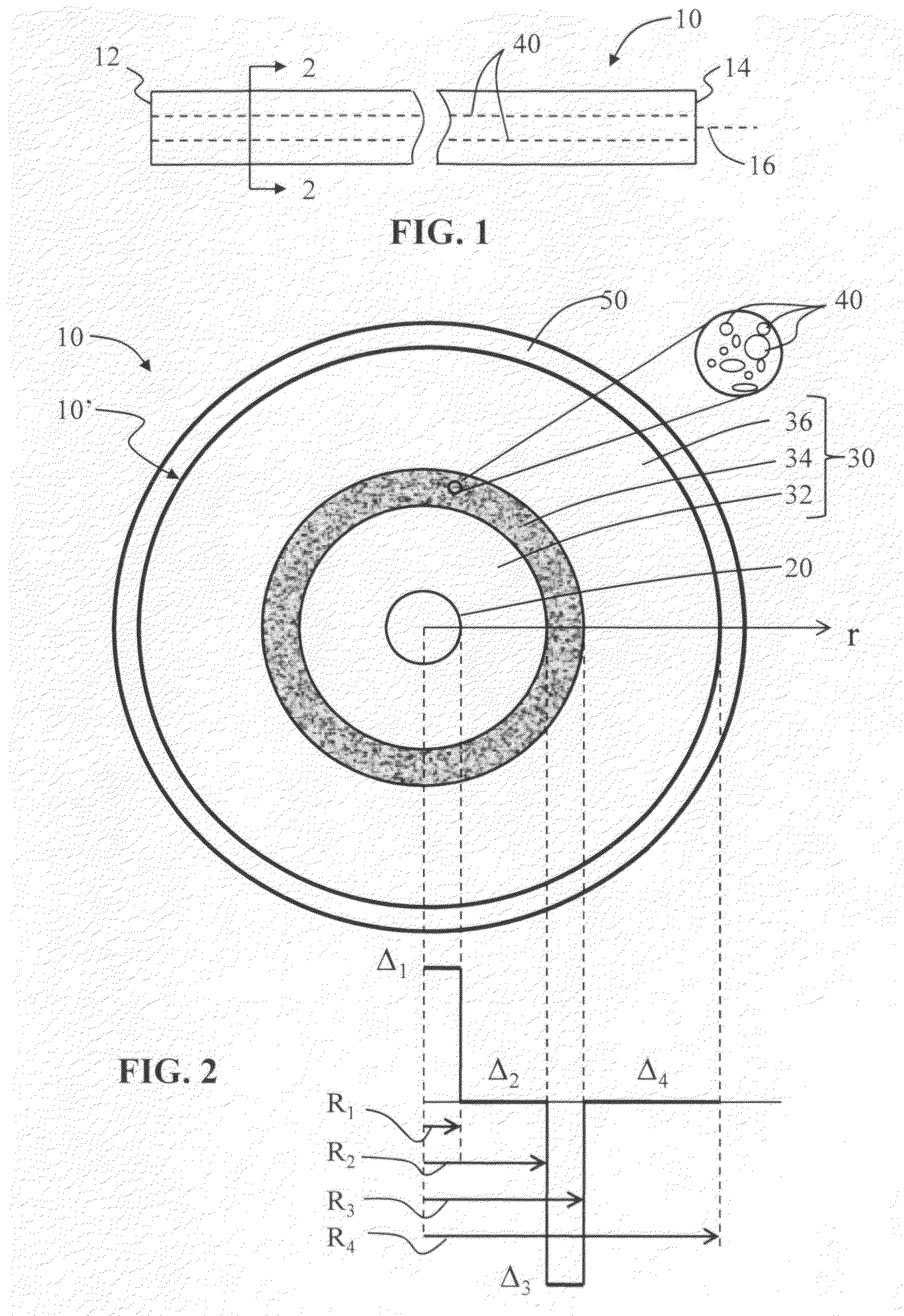
[0033]In the description below, the “refractive index profile” is the relationship between refractive index or relative refractive index and waveguide fiber radius. The “relative refractive index percent” is defined as Δi(%)=[(ni2−nc2) / 2ni2]×100, where ni is the maximum refractive index in region i, unless otherwise specified, and nc is the average refractive index of the cladding region. In an example embodiment, nc is taken as the refractive index of the inner annular cladding region 32.

[0034]As used herein, the relative refractive index percent is represented by Δ(%) or just “Δ” for short, and its values are given in units of “%”, unless otherwise specified or as is apparent...


PUM

PropertyMeasurementUnit
Temperatureaaaaaaaaaa
Timeaaaaaaaaaa

Abstract

Systems and methods of collapsing the air lines in the air line-containing region of a nanostructure optical fiber are disclosed. One method includes initiating irradiation of a portion of the nanostructure optical fiber from essentially opposite directions with at least first and second laser beams having substantially equal power and essentially the same mid-infrared wavelength. The method includes continuing the irradiation for an irradiation time t1 so as to bring the optical fiber portion to a softening temperature TS at which the air lines in the optical fiber portion collapse into the adjacent cladding. Exemplary optical systems for carrying out the air- line-collapsing methods of the present invention are also disclosed.

Description

BACKGROUND OF THE INVENTION[0001]1. Field of the Invention[0002]The present invention relates generally to nanostructured optical fibers, and in particular relates to systems for and methods of collapsing the air lines in the nanostructured region of a nanostructured optical fiber at a select location.[0003]2. Technical Background of the Invention[0004]Fiber optical systems are used for an increasing variety of telecommunication-related applications ranging from high-data-rate transmission to radio-over-fiber (ROF) to wireless system networks. With the increasing number of applications, the fiber optic cables used in such systems are being deployed in a greater variety of structures and infrastructures. Improper handling and deployment of a fiber optic cable can result in macrobending losses, also known as “extrinsic losses.” In ray-optics terms, severe bending of an optical fiber can cause the angles at which the light rays reflect within the fiber to exceed the critical angle of r...

Claims


Application Information

Patent Timeline
IPC IPC(8): C03C25/62B23K26/00
CPCG02B6/02342G02B6/02357G02B6/2552G02B6/25G02B6/02376
Inventor DANLEY, JEFFREY D.KNECHT, DENNIS M.WAGNER, ROBERT S.
Owner CORNING CABLE SYST LLC
Why Eureka
Try Eureka