Multilayer capacitor

Active Publication Date: 2005-11-15
TDK CORPARATION
View PDF16 Cites 31 Cited by
  • Summary
  • Abstract
  • Description
  • Claims
  • Application Information

AI Technical Summary

Benefits of technology

[0016]The present invention has as its object the provision of a multilayer capacitor capable of gre

Problems solved by technology

In recent years, CPUs (central processing units) used for data processing apparatuses have become higher in operating frequency and remarkably increased in current consumption due to the improvement in processing speeds and higher integration.
It has become extremely difficult to keep voltage fluctuations accompanying current fluctuations to within tolerances of the power sources.
Along with the increasingly higher operating

Method used


Image

  • Multilayer capacitor
  • Multilayer capacitor
  • Multilayer capacitor

Examples


example

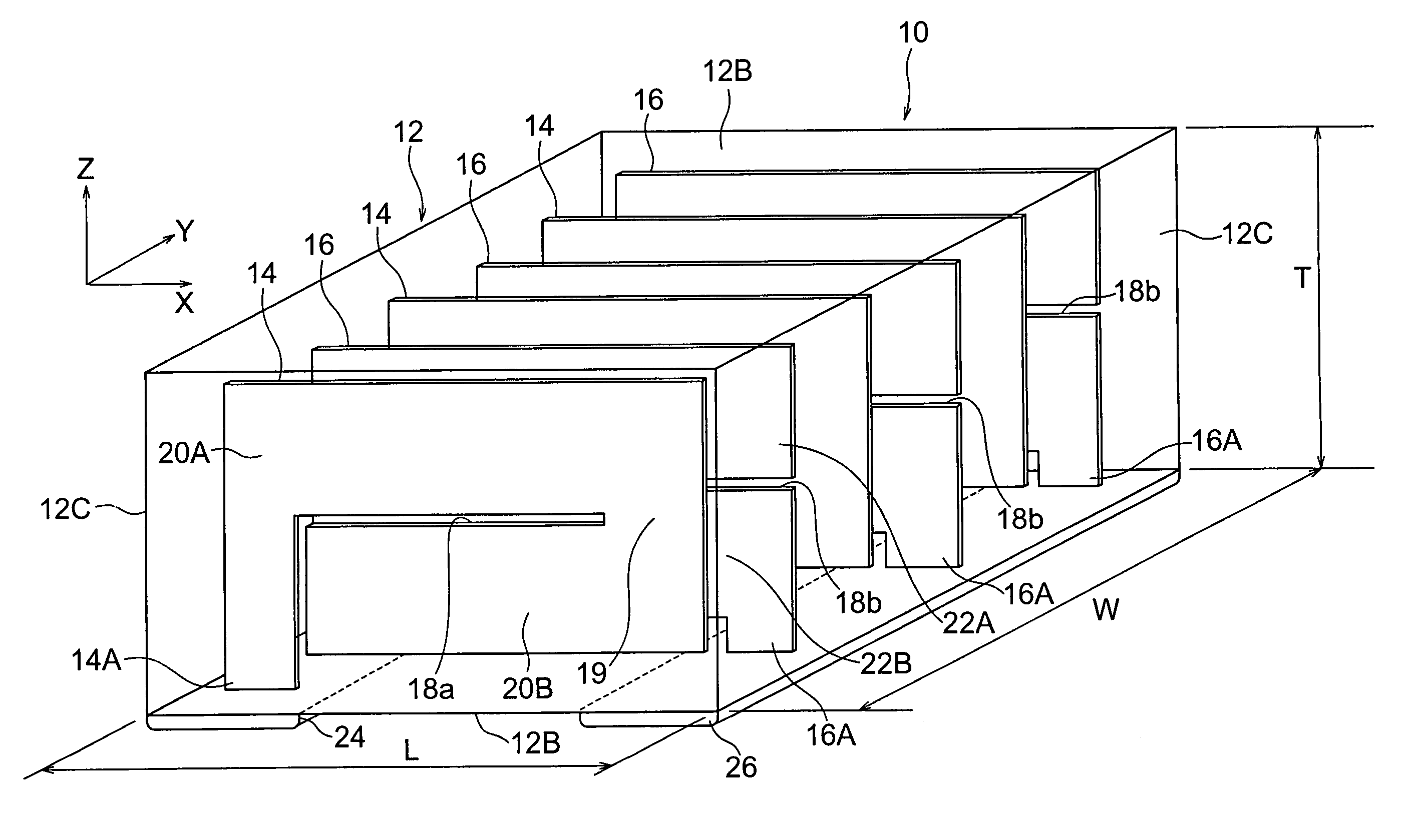
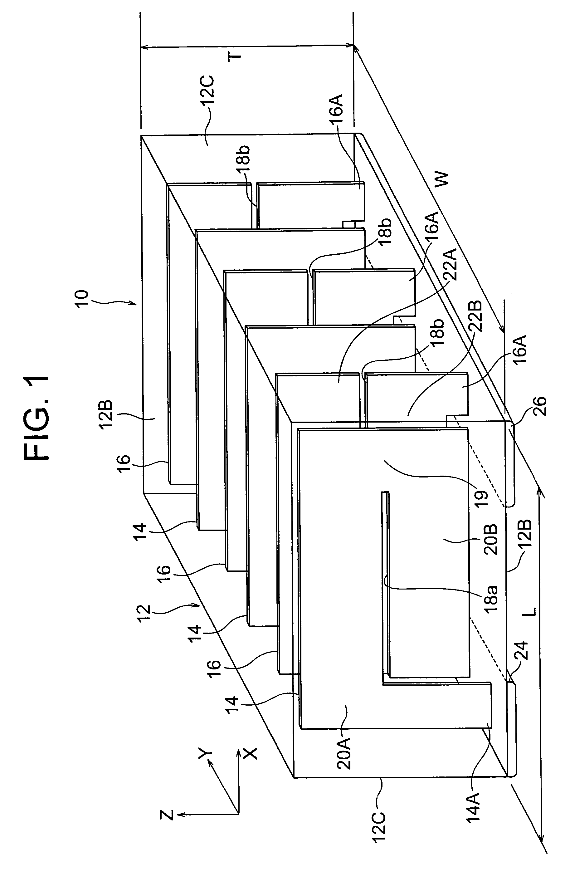
[0131]Next, a network analyzer was used to measure the S21 characteristic of the S-parameter of the following samples and find the attenuation characteristics of the samples. First, the content of the samples will be explained. That is, as the capacitor, the general multilayer capacitor shown in FIG. 14 was used as a comparative example and the multilayer capacitor according to the first embodiment shown in FIG. 1 was used as an example of the invention.

[0132]Here, the constants of the equivalent circuit were calculated so that the measured value of the attenuation characteristic and the amount of attenuation of the equivalent circuit in the multilayer capacitor 100 shown in FIG. 12 matched. Further, from the data of the attenuation characteristics of the samples shown in FIG. 11, it is learned that the amount of attenuation of the example in the high frequency band of 5 MHz or more increased by about 5 dB compared with the comparative example. Therefore, from the data, it can be un...


PUM

PropertyMeasurementUnit
Timeaaaaaaaaaa
Widthaaaaaaaaaa
Lengthaaaaaaaaaa

Abstract

A dielectric body 12 has internal conductor layers 14 arranged in it. At the far sides of the internal conductor layers 14 separated by ceramic layers 12A, internal conductor layers 16 are arranged. A length W of a side of the dielectric body 12 running along a stacking direction Y of the ceramic layers is made longer than the lengths L and T of any other two sides running along directions (X- and Y-directions) intersecting the side running along the stacking direction (Y-direction). The internal conductor layers 14 and 16 are formed with cut parts 18a and 18b, the internal conductor layers 14 are divided into channel parts 20A and 20B across the cut part 18a, and the internal conductor layers 16 are divided into channel parts 22A and 22B across the cut part 18b. These channel parts are connected through uncut ends 19, whereby the current flows in reverse directions. It is therefore possible to greatly reduce the effective inductance of the multilayer capacitor and reduce the voltage fluctuations of the CPU power source.

Description

TECHNICAL FIELD[0001]The present invention relates to a multilayer capacitor capable of greatly reducing the effective inductance, more particularly relates to a multilayer ceramic capacitor capable of reducing the voltage fluctuations of a CPU power source.BACKGROUND ART[0002]In recent years, CPUs (central processing units) used for data processing apparatuses have become higher in operating frequency and remarkably increased in current consumption due to the improvement in processing speeds and higher integration. Along with this, there is a trend toward reduction of the power consumption so as to reduce the operating voltage. Therefore, in power sources for supplying power to CPUs, faster and larger current fluctuations occur. It has become extremely difficult to keep voltage fluctuations accompanying current fluctuations to within tolerances of the power sources.[0003]Therefore, as shown in FIG. 12, a multilayer capacitor 100 called a “decoupling capacitor” is connected to a pow...

Claims


Application Information

Patent Timeline
IPC IPC(8): H01G4/30H01G4/20H01G4/005H01G4/12H01G4/018H01G4/228H02H7/16H02H7/00H01G4/012
CPCH01G4/012H01G4/30G06Q10/02G07B1/00G07B5/00G07F17/42
Inventor TOGASHI, MASAAKIONODERA, SHINYA
Owner TDK CORPARATION
Why Eureka
Try Eureka