
Network system

a network system and network technology, applied in the field of network, can solve the problems of affecting the application of the network composing the existing internet, the inability to send bandwidth information and further install a specific bandwidth securing protocol, and the inability to apply the technology disclosed, etc., to achieve the effect of easy application of the existing internet system

Inactive Publication Date: 2005-11-15
RAKUTEN GRP INC
View PDF20 Cites 22 Cited by
  • Summary
  • Abstract
  • Description
  • Claims
  • Application Information

AI Technical Summary

Benefits of technology

[0009]Accordingly, it is an object of the invention to provide a network system that achieves the optimum data transfer between a terminal unit and an application server without requiring the connection information about the bandwidth of communication line therebetween from the terminal unit.
[0010]It is a further object of the invention to provide a network system that is capable of being easily applied to the existing Internet system.

Problems solved by technology

Thereby, sending the bandwidth information and further installing a specific bandwidth securing protocol becomes unnecessary.
So, there is a problem that the system prevents the mobile terminal from being miniaturized and lightened and lays all of various terminals such as the existing Internet system under need for being equipped with the like function.
Also, it is practically difficult to apply the technology disclosed in Japanese patent application laid-open No. 11-112543 to a network composing the existing Internet.

Method used


Image

  • Network system
  • Network system
  • Network system

Examples


Embodiment Construction

[0045]The preferred embodiment of the invention will be explained below.

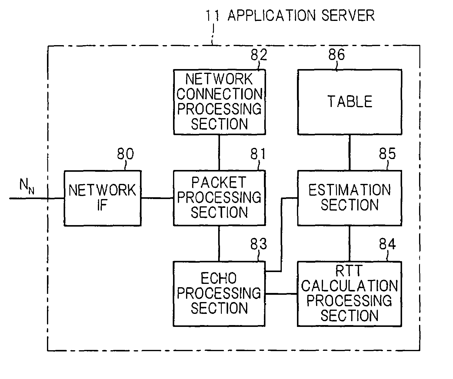
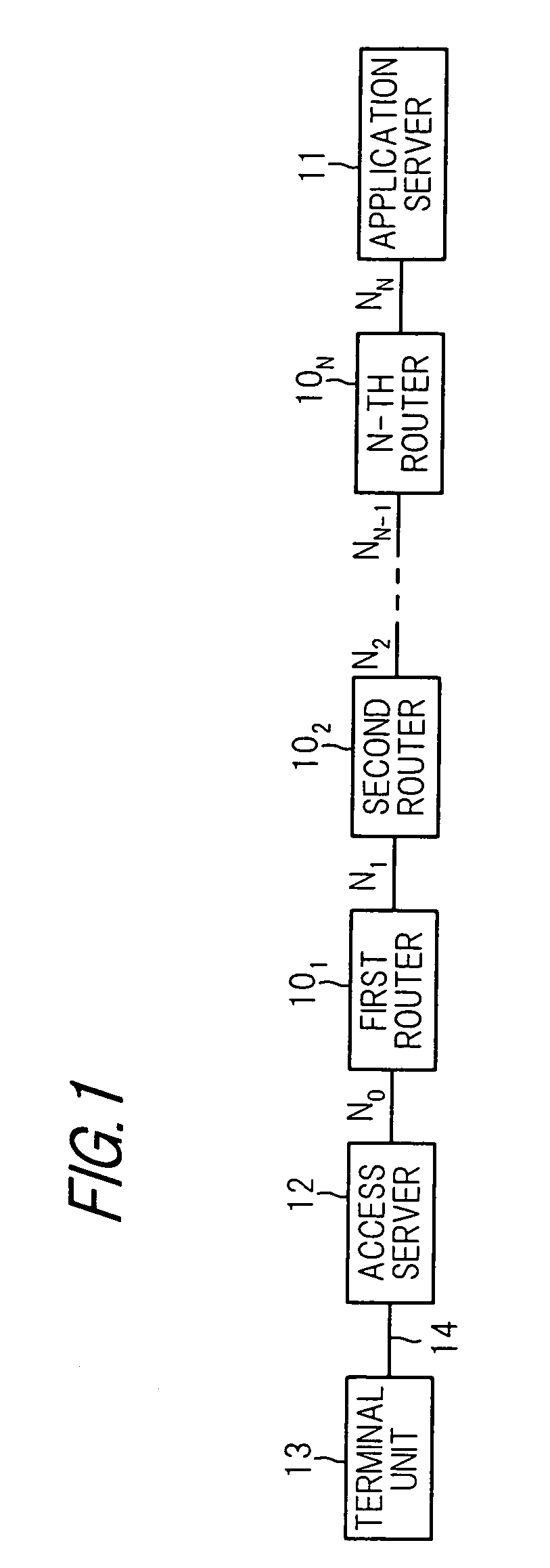
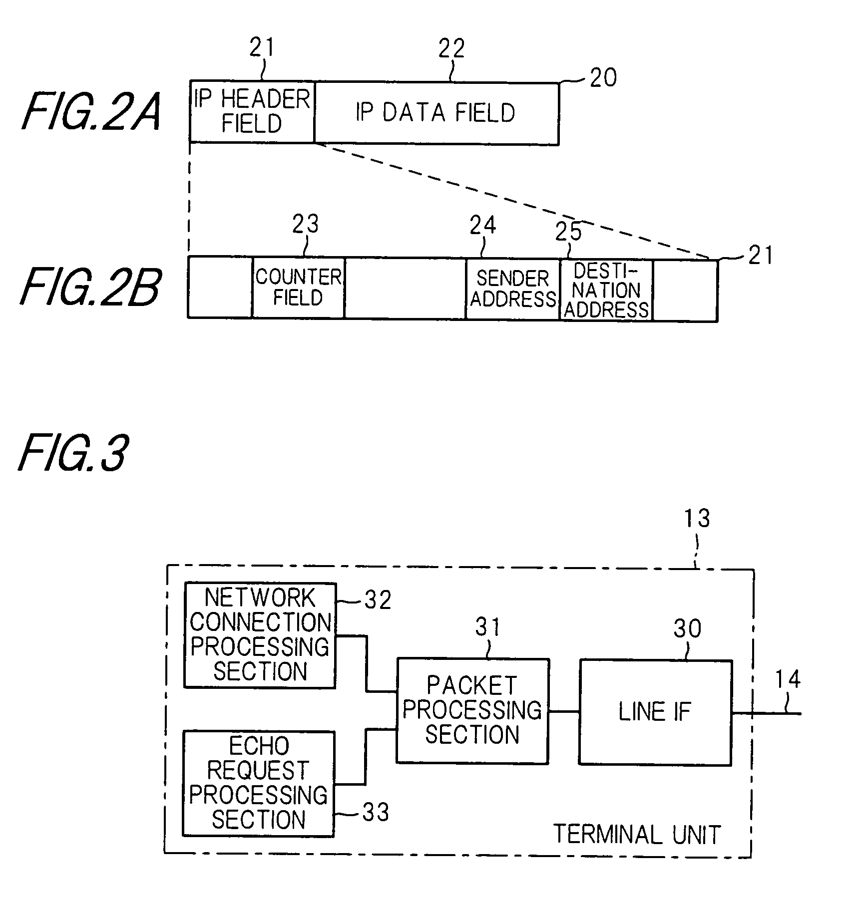
[0046]FIG. 1 shows the schematic composition of a network system in the preferred embodiment according to the invention. In the network system of the embodiment, multiple networks N0 to NN are connected through first to N-th routers 101 to 10N, respectively. The first to N-th routers 101 to 10N, respectively, conduct the repeat processing of packet data to be transferred between networks connected, on the network layer of open systems interconnection (OSI) basic reference model. Various network devices such as a personal computer are connected with the networks N0 to NN. In this example, an application server 11 to store contents data as service data for offering various services is connected with the network NN.

[0047]In getting contents data being stored in the application server 11 by accessing the Internet that is composed of the networks N0 to NN, it is necessary to connect a terminal unit to any one of the ...


PUM


Abstract

Disclosed is a network system that has: a communication line having a predetermined bandwidth; a terminal unit that is connected to the communication line and receives data through the communication line; a first unit that includes the terminal unit through the communication line and repeats data to be communicated between the terminal unit and the first unit; and a second unit that sends data to the terminal unit through the first unit according to a bandwidth of the terminal unit that is estimated based on a data delay time of the communication line.

Description

FIELD OF THE INVENTION[0001]This invention relates to a network for a terminal unit to receive various data, and more particularly to, a network system including a terminal unit that receives data transferred from a server on a network through a line.BACKGROUND OF THE INVENTION[0002]In recent years, the Internet with computer networks connected each other has been rapidly in wide use, thereby various services such as email, net news, download of moving picture or audio data and TV conference system have been supplied. The supplying of the various services is mainly supported by the enhancement in performance of computer and the progress of network communication technology. As the various services become widely used, terminal units to use the service have become also multiform. For example, as the multiform terminal units, there are home-use personal computers through conventional public telephone line, office-use computers through broadband dedicated line, and portable terminal unit...

Claims


Application Information

Patent Timeline
Patent Type & Authority Patents(United States)
IPC IPC(8): H04L12/56G06F13/00H04L12/70H04L12/801H04L12/841H04L12/911
CPCH04L47/10H04L47/18H04L47/283
Inventor MIZUKOSHI, YASUHIRO
Owner RAKUTEN GRP INC
Learn More