
Refrigerating machine

a refrigerating machine and armature winding technology, which is applied in the direction of liquid fuel engines, lighting and heating apparatus, heating types, etc., can solve the problems of armature winding dielectric breakdown and not known in detail how to enhance the overall efficiency of the refrigerating machine, and achieve the effect of enhancing the overall efficiency

Inactive Publication Date: 2005-11-22
HITACHI JOHNSON CONTROLS AIR CONDITIONING INC
View PDF10 Cites 15 Cited by
  • Summary
  • Abstract
  • Description
  • Claims
  • Application Information

AI Technical Summary

Benefits of technology

The present invention provides a refrigerating machine using multiple compressors that have a higher overall efficiency and increased reliability. The compressors are driven by motors that use an iron core and a permanent magnet to create a synchronous motor. The compressors can be driven at both a commercial power source and a variable frequency by an inverter. The machine also includes a scroll compressor and concentrically wound armature windings in the stator. If the inverter fails, the compressors can still be driven by the commercial power source. The compressors are all driven by motors that have an iron core and a squirrel cage conductor, and a pressure detecting device is included to regulate the compressor's discharge pressure.

Problems solved by technology

However, although the compressor subjected to an inverter drive is driven with a relatively high degree of efficiency in the above-mentioned configuration, it has been not yet known in detail how to enhance the overall efficiency of the refrigerating machine.
In the case of synchronous operation of the built-in magnet synchronous motor, overload operation causes the built-in magnet synchronous motor to produce an insufficient torque which deteriorates the synchronous operation so that the armature stalls, result in running of abnormal current therethrough, and accordingly, there would cause a risk of occurrence of a dielectric breakdown of the armature windings.

Method used


Image

  • Refrigerating machine
  • Refrigerating machine
  • Refrigerating machine

Examples


Embodiment Construction

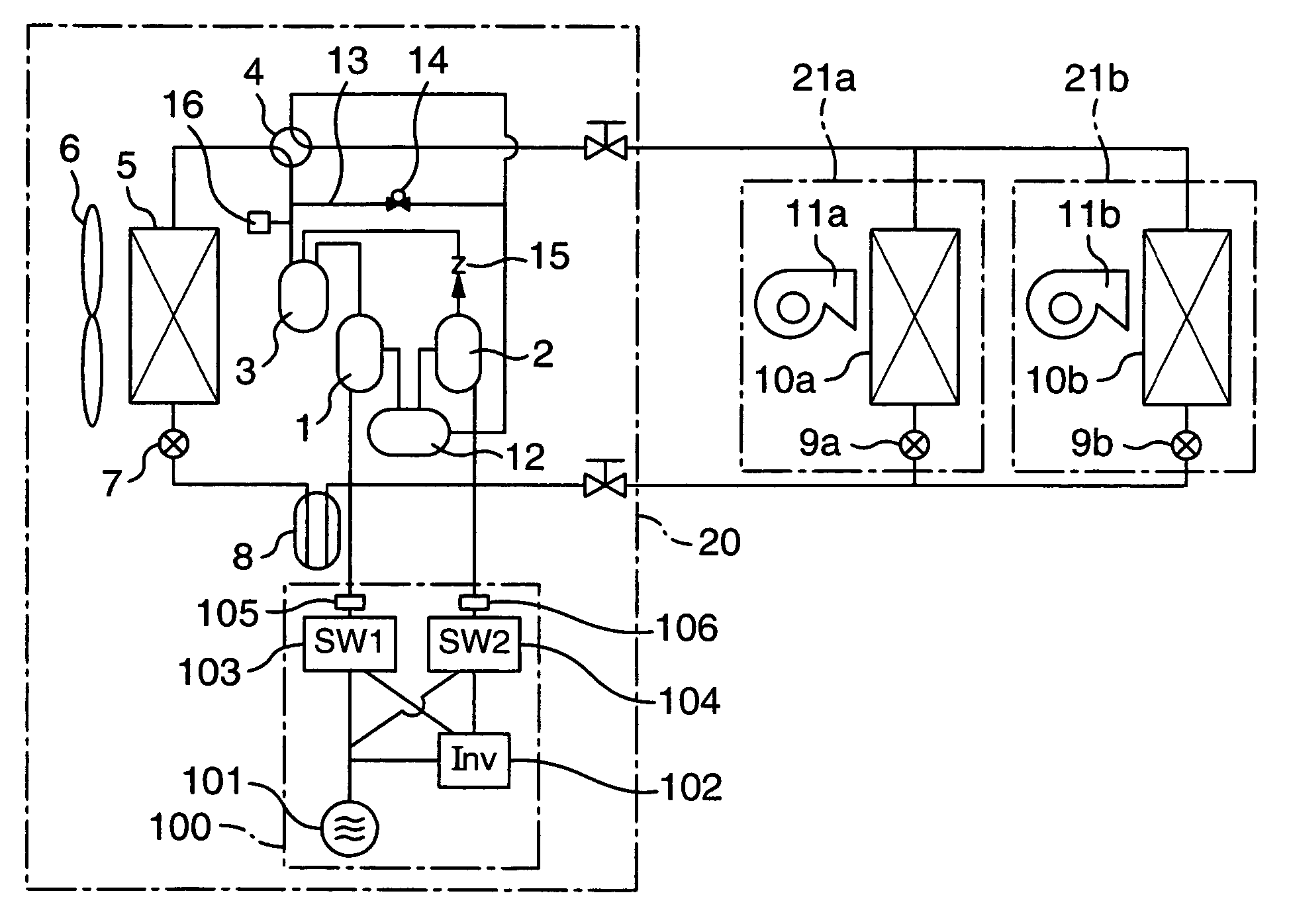
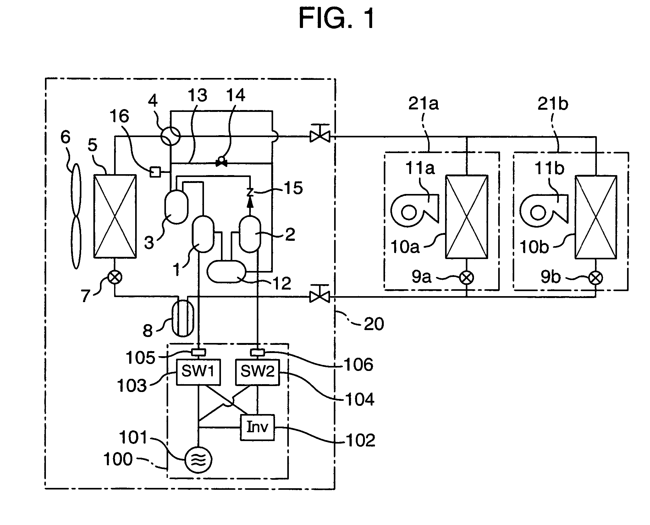
[0029]Referring to FIG. 1 which shows a refrigerating cycle of an air-conditioner having two compressors 1, 2, there are shown a variable speed compressor 1 driven by an inverter and a constant speed compressor 2 driven by a commercial power source. Each of the compressors 1, 2 incorporates therein a built-in magnet synchronous motor (a self-start type synchronous motor) having an armature provided with a squirrel cage conductor which allows the motor to serve as an induction motor, and a permanent magnet which is bipolar-magnetized so as to allow the motor to serve as a synchronous motor. Further, a four way valve 4, an outdoor heat-exchanger 5, an outdoor expansion valve 7, a receiver 8, indoor expansion valves 9a, 9b, indoor heat-exchangers 10a, 10b and an accumulator 12 are connected in the mentioned order by means of a refrigerant pipe line so as to constitute a refrigerating cycle.

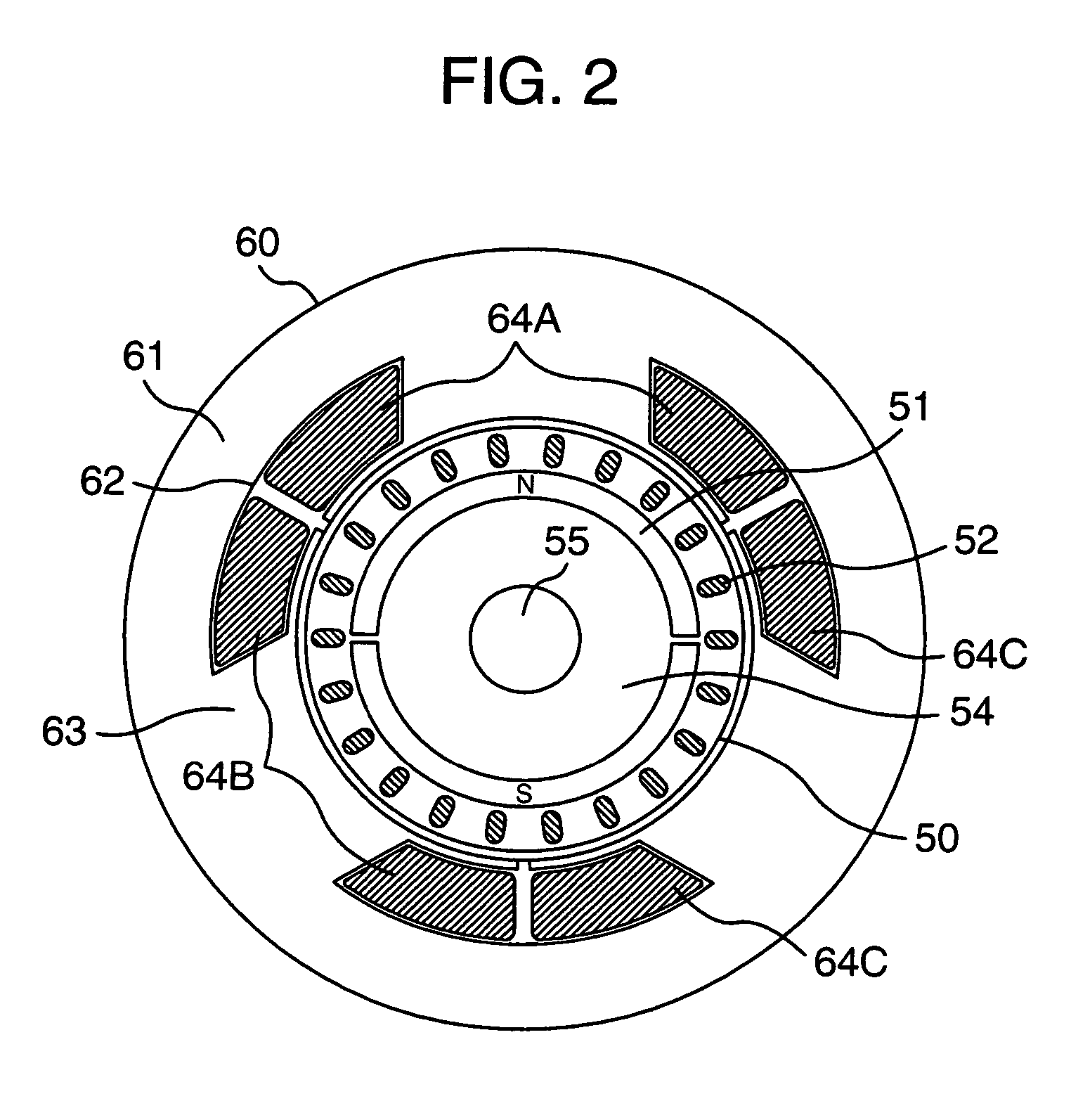
[0030]Referring to FIG. 2 which is a detailed sectional view in a diametrical direction of the mo...


PUM


Abstract

A refrigerating machine having a compressor driven by a motor. The motor incorporates an armature with an iron core having a cage type conductor and a permanent magnet which is magnetized so as to enable the motor to operate as a synchronous motor. A bypass passage is provided between a discharge side of the compressor and a suction side of the compressor, a shut-off valve is provided for opening and closing the bypass passage, a pressure detecting device is provided for detecting a discharge pressure from the compressor and a current detector is provided for detecting a value of drive current for the compressor. The shut-off valve is opened and closed in accordance with the discharge pressure and the value of the drive current.

Description

CROSS REFERENCE TO RELATED APPLICATION[0001]This is a continuation of U.S. application Ser. No. 10 / 614,018, filed Jul. 8, 2003 now U.S. Pat. No. 6,832,488, the subject matter of which is incorporated by reference herein.BACKGROUND OF THE INVENTION[0002]The present invention relates to a refrigerating machine such as a refrigerator or an air-conditioner, using a vapor compression refrigerating cycle.[0003]These years, due to a tendency of increase demands of prevention of earth warming and reduction in running cost, energy saving as to refrigerators and air-conditioners which causes energy consumption in a large part in tenants and buildings has been promoted. In order to enhance the efficiency of a refrigerating machine such as an air-conditioner or a refrigerator and to lower the costs thereof, as disclosed in JP-A-2001-227778, it has been known to use a built-in magnet synchronous motor for driving a compressor, having an armature incorporating a squirrel cage conductor and a perm...

Claims


Application Information

Patent Timeline
Patent Type & Authority Patents(United States)
IPC IPC(8): F04C18/02F04C23/00F25B49/02F25B1/00F04C28/08F24F5/00F25B1/04
CPCF04C18/0215F04C23/003F04C23/008F04C28/08F25B49/025F04C2240/403F25B2400/0751F25B2500/26F25B2600/021F25B2600/0251F25B2700/1931Y02B30/741Y02B30/70F24F5/00
Inventor YOKOZEKI, ATSUHIKONAKAYAMA, SUSUMUTOJO, KENJISARUTA, AKIRAMATSUNAGA, MUTSUNORIKIKUCHI, SATOSHI
Owner HITACHI JOHNSON CONTROLS AIR CONDITIONING INC
Learn More