
Hydraulic ratchet wrench with double-action hydraulic cylinder piston drive

a hydraulic cylinder and hydraulic ratchet technology, which is applied in the direction of portable percussive tools, boring/drilling equipment, drilling machines and methods, etc., can solve the problem of hydraulic oil flowback and other problems

Inactive Publication Date: 2005-11-22
KIPFELSBERGER ALEXANDER
View PDF6 Cites 3 Cited by
  • Summary
  • Abstract
  • Description
  • Claims
  • Application Information

AI Technical Summary

Benefits of technology

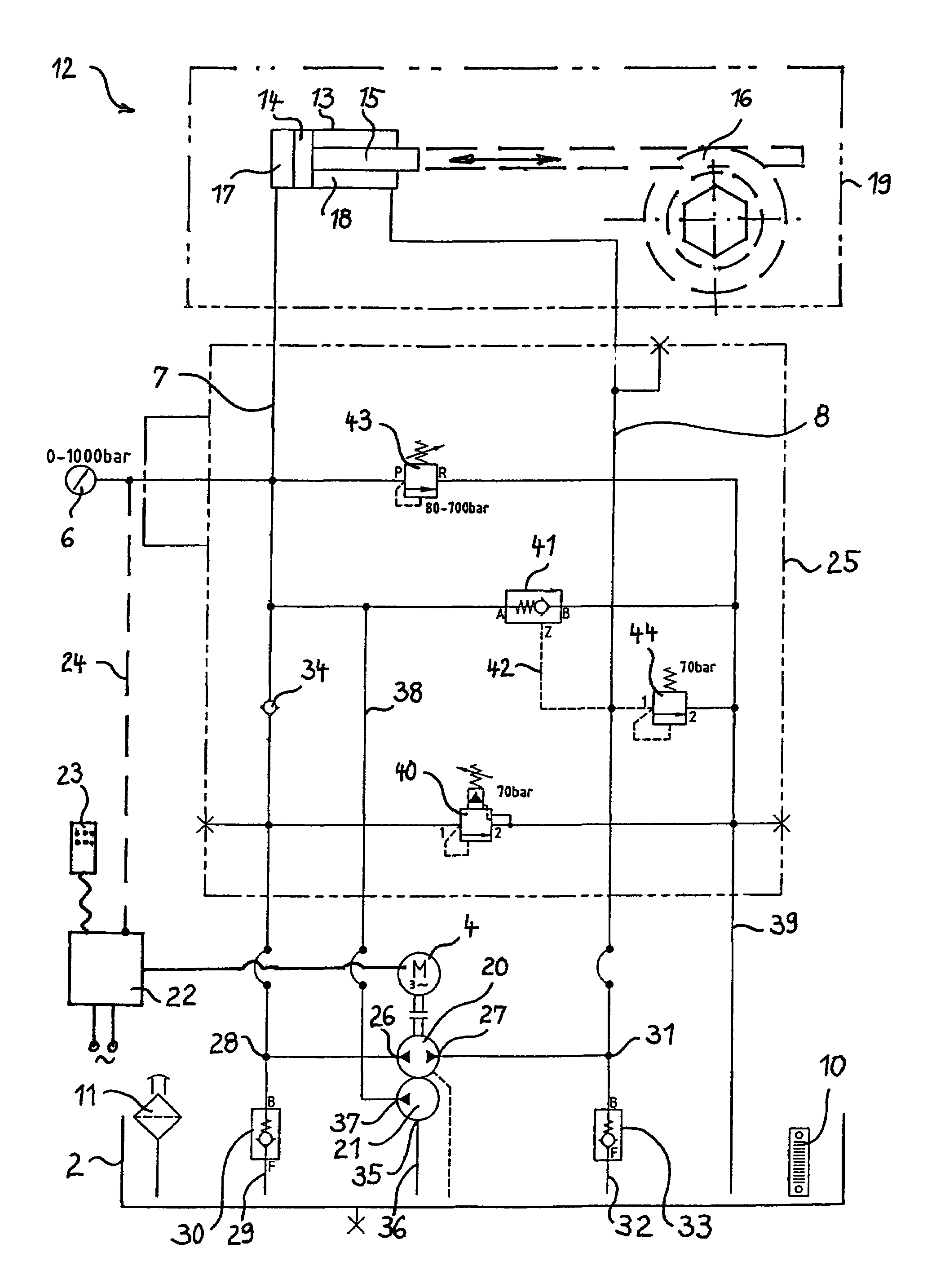
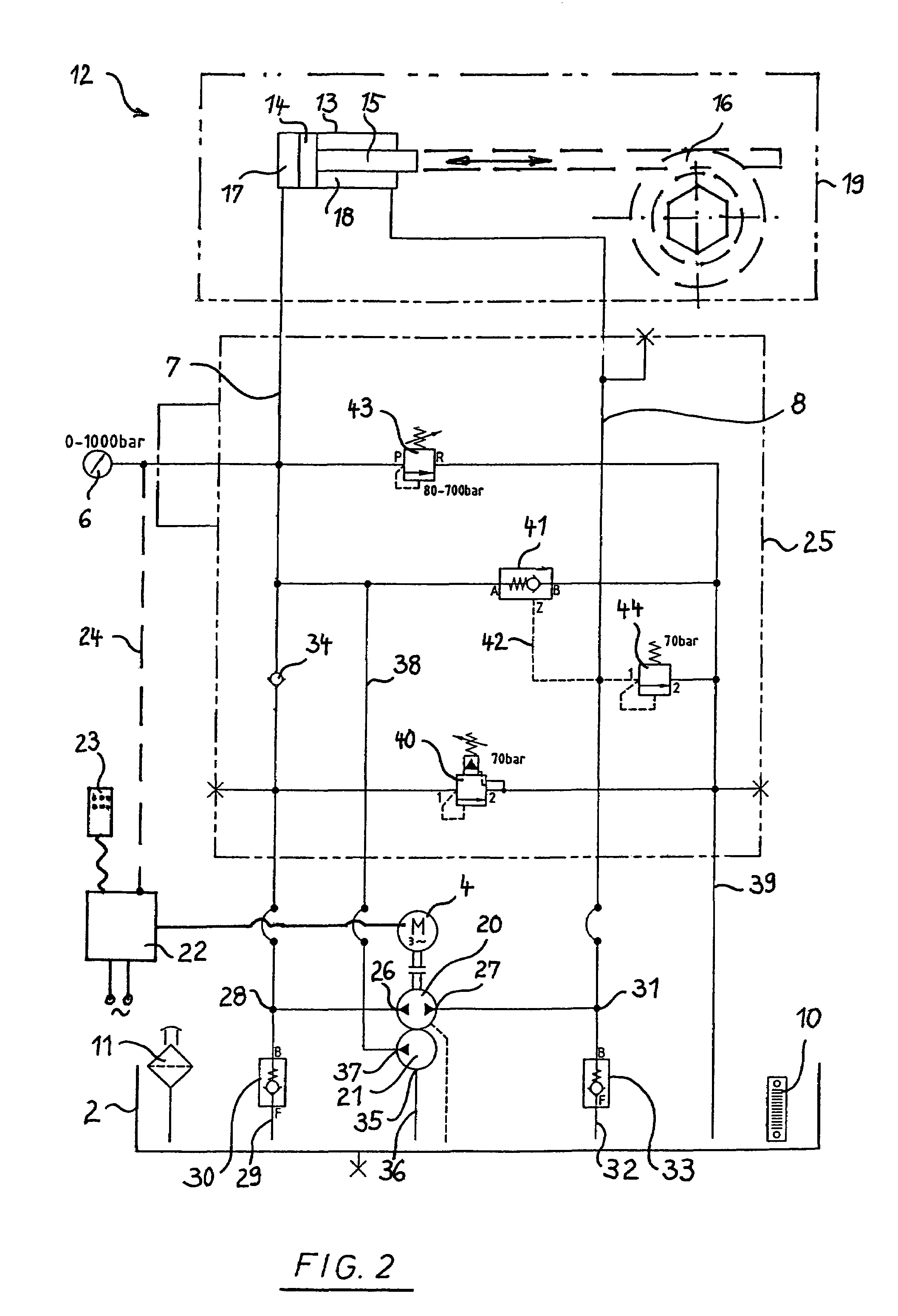
[0011]The advantageous result of the above arrangement is that the gear pump produces a rapid piston advance at high conveying capacity at the beginning of a working stroke, e.g., up to 6 liters per minute. Thus, the conveying capacity of the radial piston pump is also increased. For the required associated emptying of the return stroke chamber, the latter is connected for flow with the other gear pump connection acting as an suction connection. Since the volume of hydraulic oil flowing into the working stroke chamber is greater than the hydraulic oil volume displaced from the return stroke chamber due to the volume of the piston rod, the gear pump is able to suction the difference in volume through the second suction port and the second suction check valve.
[0013]For a return stroke, the pump motor is actuated for rotation in the opposite direction so that the gear pump also conveys in the opposite direction. As a result, hydraulic oil is pumped into the return stroke chamber whereby the working stroke chamber is open for a return of hydraulic oil to the oil tank via the open unblocking check valve. A relatively low quantity of conveyed matter from the radial piston pump is added in this case to the return flow volume. Great pressure build-up in the return stroke chamber by the radial piston pump is not possible with this arrangement. A rapid retraction of the piston or of the piston rod is thereby advantageously achieved. For the return stroke only a change of the motor's direction of rotation is required whereby the valves used adjust themselves automatically in the arrangement as needed and without outside control. Conventional sealing rings on the piston can be subjected to high pressure only from the side of the working stroke chamber. This is taken into account with the present arrangement since only the gear pump takes effect in the return stroke chamber with maximum pressure of approximately 100 bar, thus the rings are secured. Contrary to the state of the art where a switch-over from working stroke to return stroke is effected by several expensive and malfunction-prone valves that are also controlled from the outside, only control for the reversal of the direction of rotation of the pump motor is required here whereby the valves used adjust themselves correctly and without outside energy. The design of the arrangement according to the present invention is therefore much simpler, less expensive, more compact and less heavy. The volume of the oil tank, in particular, can be smaller and the hydraulic oil does not heat up as much in operation.

Problems solved by technology

Thus a flowback of hydraulic oil is released from the working stroke oil line to the oil tank when a given low pressure has been reached.

Method used


Image

  • Hydraulic ratchet wrench with double-action hydraulic cylinder piston drive
  • Hydraulic ratchet wrench with double-action hydraulic cylinder piston drive
  • Hydraulic ratchet wrench with double-action hydraulic cylinder piston drive

Examples


Embodiment Construction

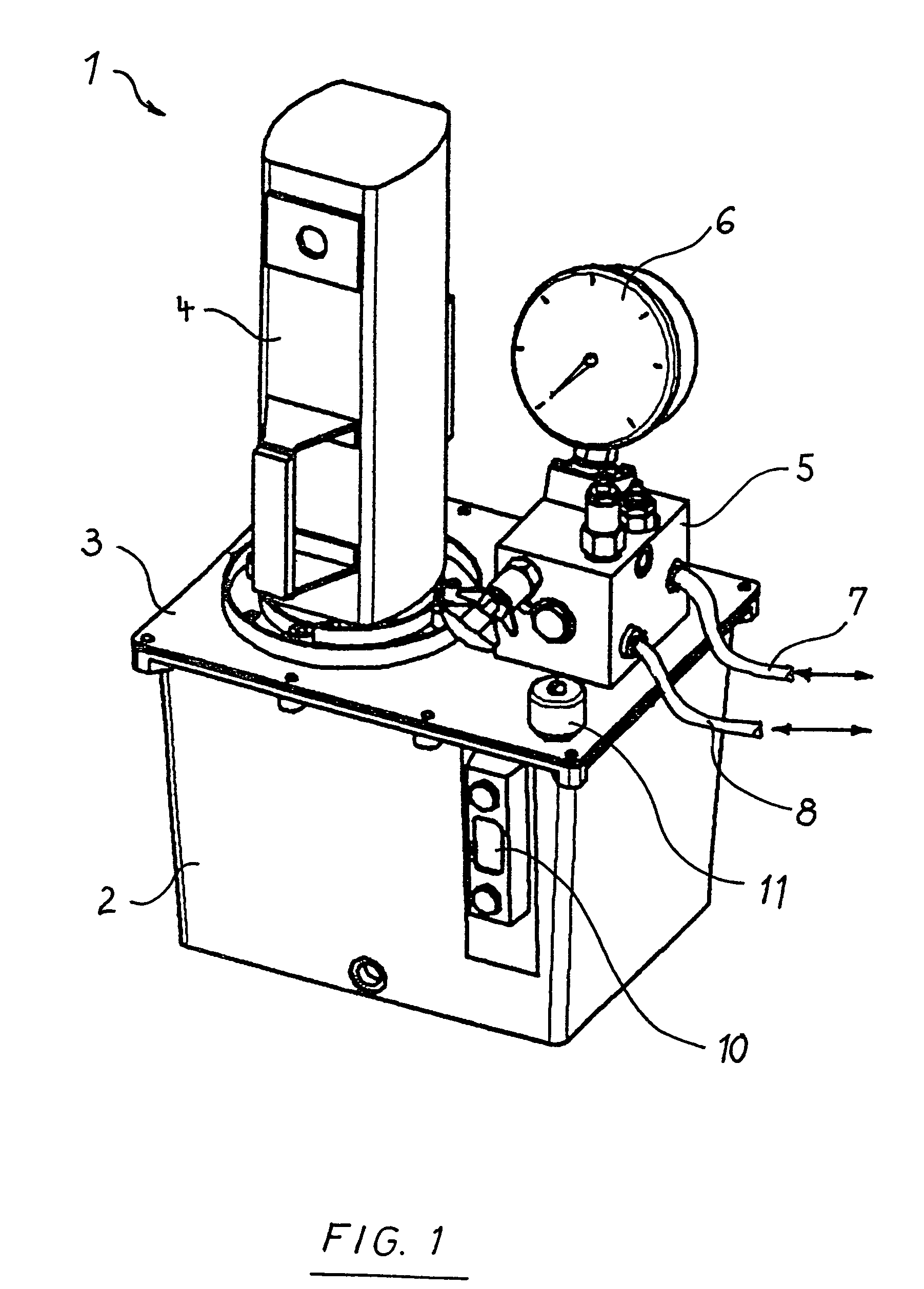
[0024]FIG. 1 shows the design of the hydraulic pump apparatus 1 of a hydraulic ratchet wrench. An oil tank 2 for hydraulic oil is covered by a covering plate 3 on which a pump motor 4 with vertical motor drive shaft is mounted. A gear pump (not shown here) and a radial piston pump driven by the motor drive shaft are installed in the oil tank 2. A hydraulics control unit 5 is mounted on the covering plate 3 and its circuit layout is described through FIG. 2. A high-pressure manometer 6 is connected to the hydraulics control unit 5. In addition, actuators for stop valves and control valves are shown. From the hydraulics control unit 5, a working stroke oil line 7 and a return stroke oil line 8 lead to a hydraulic cylinder 9 not shown here. Also shown are a tank level indication 10 and a tank ventilation system 11.

[0025]FIG. 2 schematically shows a hydraulic ratchet wrench 12 in combination with a hydraulic circuit diagram. A piston in the form of a disk piston 14 is located in hydraul...


PUM

PropertyMeasurementUnit
Pressureaaaaaaaaaa
Pressureaaaaaaaaaa
Pressureaaaaaaaaaa

Abstract

The invention relates to a hydraulic ratchet wrench with a double-action hydraulic cylinder piston drive with a gear pump (20) and a piston pump (21). According to the invention, a working stroke and a return stroke are controlled through a reversal of rotational direction of a pump motor (4), whereby the necessary flow volume is produced automatically via internal flow control valves, and without additional valve controls.

Description

[0001]The invention relates to a hydraulic ratchet wrench with a double-action hydraulic cylinder having a piston drive with a gear pump and a piston pump. According to the invention, a working stroke and a return stroke are controlled through a reversal of rotational direction of a pump motor, whereby the necessary flow volume is produced automatically via valve arrangements, without additional valve control.BACKGROUND OF THE INVENTION[0002]In generally known hydraulic ratchet wrenches with double-action hydraulic cylinders, a piston is movable within the hydraulic cylinder as a disk piston with a piston rod tightly protruding from the hydraulic cylinder for ratchet actuation. Within the hydraulic cylinder, the displaceable piston constitutes a working stroke chamber as a high-pressure chamber on one side of the piston, and a return stroke chamber as a low-pressure chamber on the piston side with the piston rod.[0003]The known hydraulic ratchet wrench furthermore comprises a two-ph...

Claims


Application Information

Patent Timeline
IPC IPC(8): B25B21/00F15B7/00F15B7/04
CPCB25B21/005B25B23/145F15B7/001F15B7/006F15B7/04
Inventor KIPFELSBERGER, ALEXANDER
Owner KIPFELSBERGER ALEXANDER
Learn More