High quality optically polished aluminum mirror and process for producing

a technology of optically polished aluminum and production process, which is applied in the direction of optical surface grinding machine, manufacturing tool, edge grinding machine, etc., can solve the problems of poor surface polishing, reduced surface roughness, and inability to readily implement bare aluminum as an acceptable mirror material for uv, and achieves superior accuracy.

Inactive Publication Date: 2005-11-22
UNITED STATES GOVERNMENT AS REPRESENTED BY THE ADMINISTATIO OF THE NAT AERONAUTICS & SPACE ADMINISTATION
View PDF22 Cites 9 Cited by
  • Summary
  • Abstract
  • Description
  • Claims
  • Application Information

AI Technical Summary

Benefits of technology

[0014]Properly implemented, therefore, the proposed innovation will eliminate many of the associated problems now common with current aluminum mirror technology, delivering aluminum optics with superior accuracy.

Problems solved by technology

Due to light scattering, which results from poorly polished surfaces, however, bare aluminum cannot be readily implemented as an acceptable mirror material for UV, IR, and visible applications.
The result creates a tradeoff whereby surface roughness is decreased while thermal and mechanical stability of the optic are severely compromised at all but room temperatures.
Further complicating matters is the fact that the mount is usually an integrally machined part of an aluminum optic.
While these characteristics are great for dimensional requirements and ease of design, they create havoc on the optical performance once all surfaces are evenly plated with nickel.
The electroless nickel platings also can cause bi-metallic stresses to deteriorate optical performance.
Another problem of plating aluminum with electroless nickel is that manufacturing costs grow because nickel polishes more slowly than conventional optical materials.

Method used


Image

  • High quality optically polished aluminum mirror and process for producing
  • High quality optically polished aluminum mirror and process for producing
  • High quality optically polished aluminum mirror and process for producing

Examples


Embodiment Construction

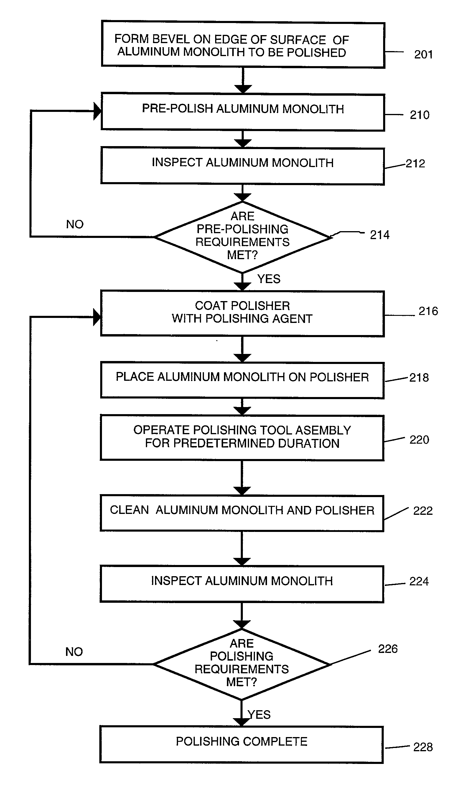
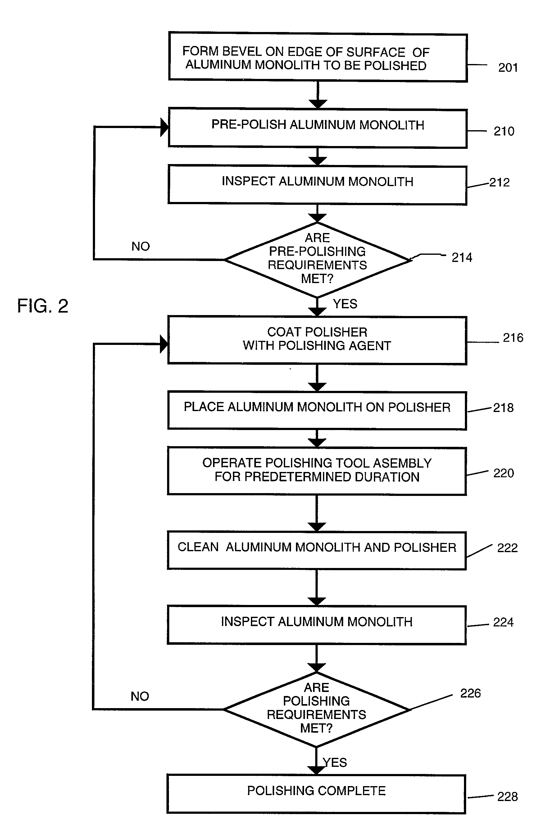
[0019]This present invention provides an aluminum mirror of less than about 30 angstroms rms and preferably about 5 angstroms rms surface roughness with surface accuracy in terms of surface figure error as low as one-fifteenth of a wave peak-to-valley. The inventors used commercial grade aluminum, for example, 6061-T6 aluminum, to produce the aluminum mirror presented by this invention. Inventors believe that further polishing of the aluminum mirror mentioned above with the polishing process proposed by this invention can produce an aluminum mirror of higher quality.

[0020]The polishing process proposed by this invention can be applied to other optically feasible substrates including glass, nickel, stainless steel, and many other glasses or metal materials.

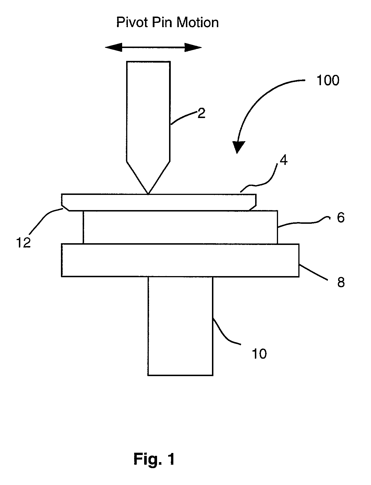
[0021]Referring to FIG. 1, the polishing operation is performed by the precise assembly of components to create a polishing tool assembly 100. A select grade of pitch used exclusively for optical fabrication is melted and poured on...


PUM

PropertyMeasurementUnit
surface roughnessaaaaaaaaaa
sizeaaaaaaaaaa
surface roughnessaaaaaaaaaa

Abstract

A new technical advancement in the field of precision aluminum optics permits high quality optical polishing of aluminum monolith, which, in the field of optics, offers numerous benefits because of its machinability, lightweight, and low cost. This invention combines diamond turning and conventional polishing along with india ink, a newly adopted material, for the polishing to accomplish a significant improvement in surface precision of aluminum monolith for optical purposes. This invention guarantees the precise optical polishing of typical bare aluminum monolith to surface roughness of less than about 30 angstroms rms and preferably about 5 angstroms rms while maintaining a surface figure accuracy in terms of surface figure error of not more than one-fifteenth of wave peak-to-valley.

Description

CROSS-REFERENCES TO RELATED APPLICATIONS[0001]This Application is a Continuation-In-Part of application Ser. No. 09 / 492,085 filed Jan. 27, 2000, “High Quality Optically Polished Aluminum Mirror and Process for Producing,” now U.S. Pat. No. 6,350,176.ORIGIN OF THE INVENTION[0002]The invention described herein was made by employees of the United States Government. The invention may be manufactured and used by or for the governmental purposes without the payment of royalties thereon or therefor.FIELD OF THE INVENTION[0003]The present invention relates to polishing an optic surface and more particularly to polishing an optic surface on an aluminum monolith.BACKGROUND OF THE INVENTION[0004]Metallic mirrors have been widely used for instruments in space and military applications. System performance of the instruments is largely dependent upon the reflective surface of the mirror. Performance of the optical mount, and its thermal and mechanical characteristics also have effects on the perf...

Claims


Application Information

Patent Timeline
Patent Type & Authority Patents(United States)
IPC IPC(8): B24B1/00B24B9/14B24B13/00B24B13/015
CPCB24B9/14B24B13/0018B24B13/015
Inventor LYONS, III, JAMES J.ZANIEWSKI, JOHN J.
Owner UNITED STATES GOVERNMENT AS REPRESENTED BY THE ADMINISTATIO OF THE NAT AERONAUTICS & SPACE ADMINISTATION
Why Eureka
Try Eureka