Durable, open-faced retroreflective prismatic construction

a prismatic and retroreflective technology, applied in the field of durable, open-faced retroreflective prismatic construction, can solve the problems of limited prismatic material and diminished performance capabilities

Inactive Publication Date: 2005-11-22
ORAFOL AMERICAS
View PDF40 Cites 106 Cited by
  • Summary
  • Abstract
  • Description
  • Claims
  • Application Information

AI Technical Summary

Benefits of technology

[0013]1. The open structures can be filled with clear or colored resins to improve the entrance angle, change the color, reduce curling, increase adhesion to the cover film, etc.
[0020]8. Low refractive index coatings may be used in place of the metalized coating to provide high whiteness open-faced structures or chips that can be mixed into high refractive index binders.

Problems solved by technology

Thus, the prism material is limited to materials which have this property.
Unfortunately, it has been found that these materials are often susceptible to ultraviolet (UV) light, visible light, and / or thermal degradation, resulting in diminished performance capabilities.

Method used


Image

  • Durable, open-faced retroreflective prismatic construction
  • Durable, open-faced retroreflective prismatic construction
  • Durable, open-faced retroreflective prismatic construction

Examples


example 1

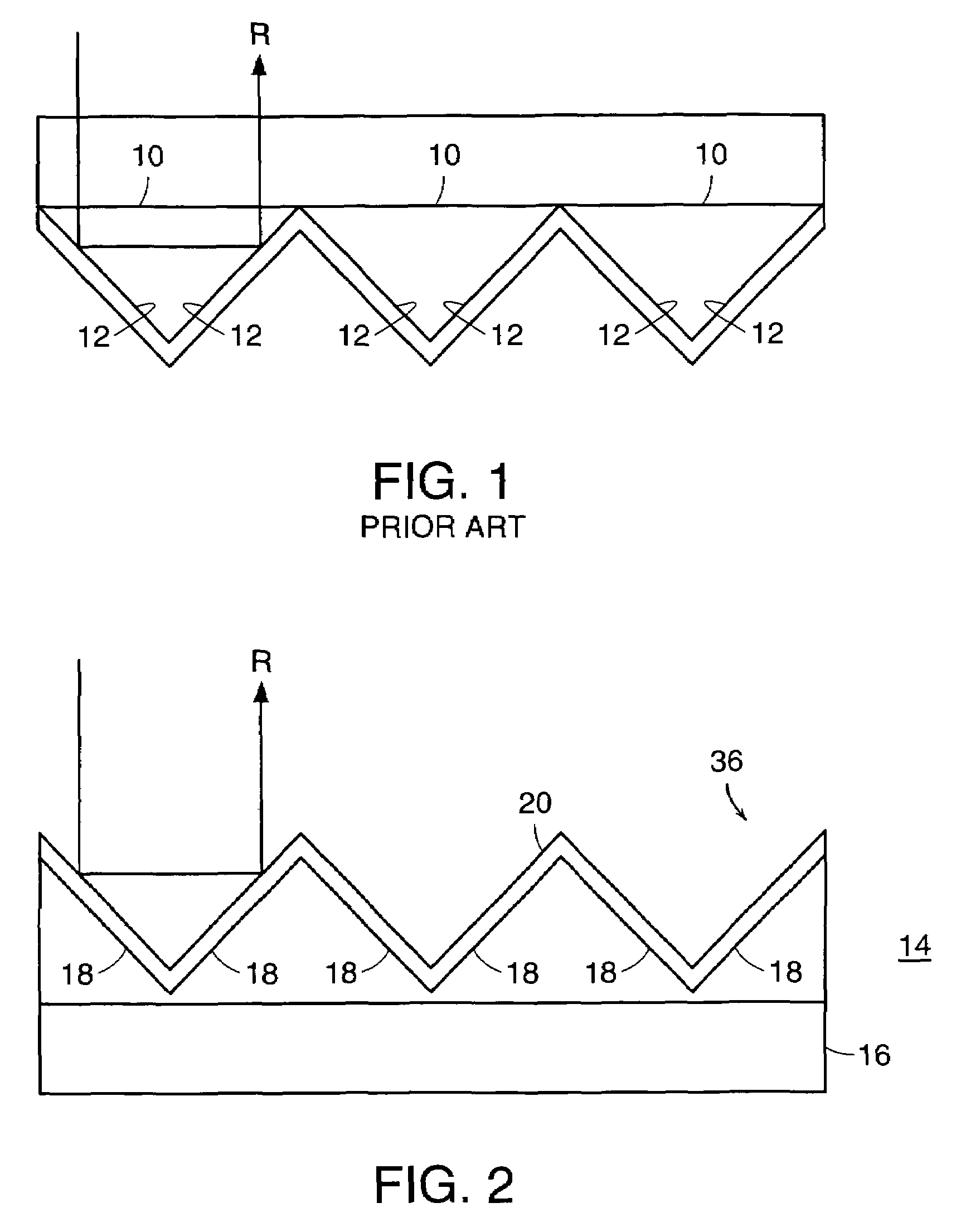
[0104]A structure of 50.8 μm (2 mil) pitch open-faced prisms was cast onto 50.8 μm (2 mil) polyester film with a UV curable epoxy-acrylate resin. The structure was coated with a thin film of vacuum deposited aluminum in order to produce the retroreflective surfaces. Samples were characterized as having a set of illumination angles (SIA), also known as entrance angles values, of over 300 candelas / lux / sq.m. at 0.2 observation and −4 entrance angles. A protective top coating of urethane-acrylate resin was coated on the face of the material and it was aged in an Atlas Xenon Weatherometer with the ASTM G26 cycle. The initial reading of 309 SIA dropped to 131 SIA after 4,000 hours in the weatherometer. The maintenance of over 40% of the initial reflective brightness is considered to be unusually good for this type of prism resin.

example 2

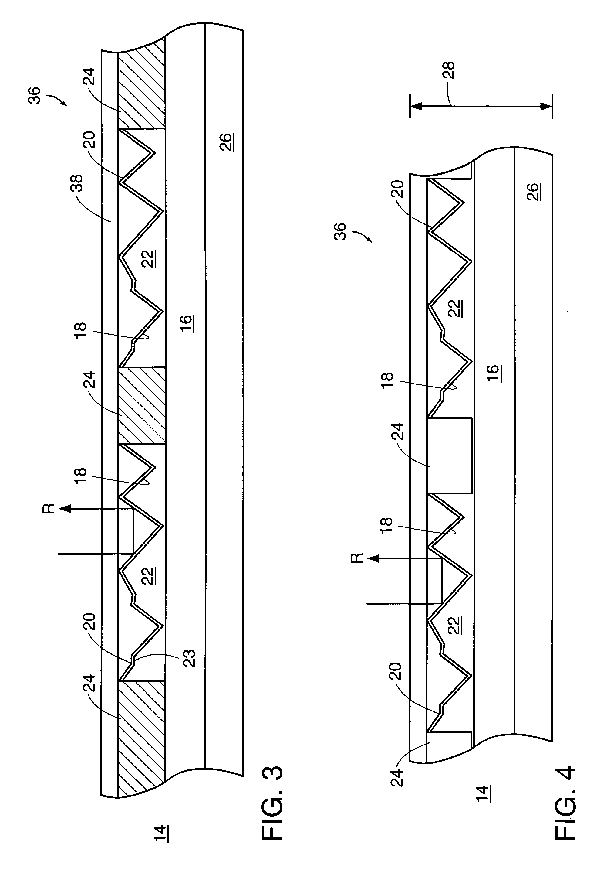
[0105]A structure of 50.8 μm (2 mil) pitch open-faced prisms was cast onto a polyester film with a UV curable epoxy-acrylate resin. The structured surface was vacuum coated with aluminum to produce a retroreflective material. A protective layer of acrylic film, VCF a-223, that had been coated with a thin adhesive layer of Rohm and Haas, Paraloid F-10, was thermally laminated to the retroreflective face at 121 degrees Celsius (250 degrees Fahrenheit) and 27.8 kPa (4 psi). The sample displayed a retroreflective value of over 300 SIA units at 0.2 degree observation and −4 degree entrance angle.

example 3

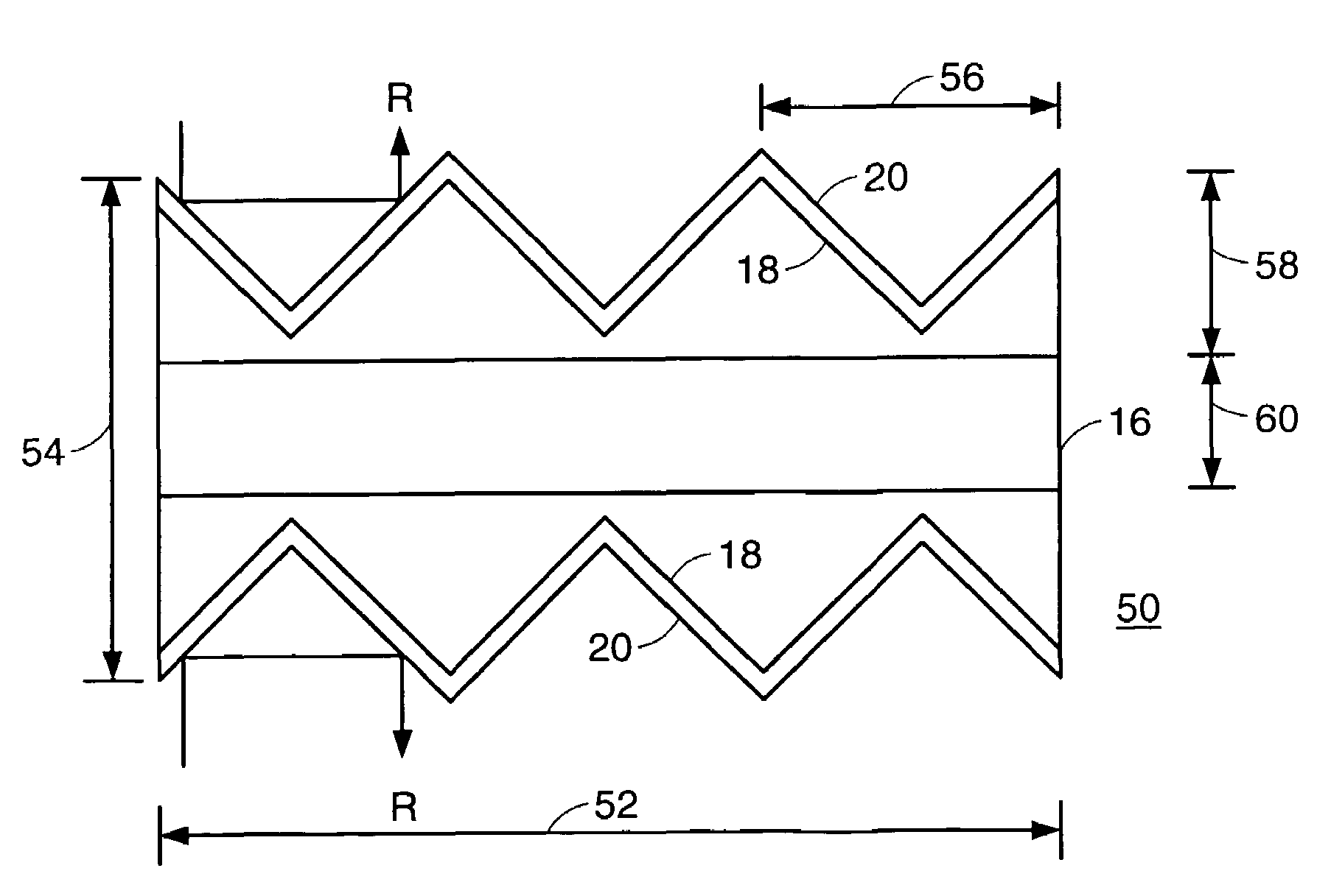
[0106]A structure of 50.8 μm (2 mil) pitch open-faced prisms was cast onto a polyester film carrier with a UV curable epoxy-acrylate resin. The structured surface was vapor coated with aluminum to produce a retroreflective material. The retroreflective face was then screen printed with a white acrylic caulking compound, DAP, and a layer of acrylic film was laminated to the printed pattern while it was still tacky. The sample displayed a retroreflective value of over 300 SIA units. A 25.4 μm (1 mil) polyester film that had been coated with 25.4 μm (1 mil) of acrylic pressure sensitive adhesive (PSA) on each side and covered with two layers of silicone coated polyester film was used as the carrier. Open-faced prism structures were sequentially cast onto the two PSA surfaces and the sample was aluminum metalized to produce a thin material that was 139.7 μm (5.5 mil) thick and had retroreflective elements on both sides.


PUM

PropertyMeasurementUnit
thicknessaaaaaaaaaa
thicknessaaaaaaaaaa
thicknessaaaaaaaaaa

Abstract

Retroreflective sheeting and a method for making the same includes a plurality of open-faced cube-corner surfaces formed from a substantially rigid material to keep the cube-corner surfaces from flexing. An optical coating is formed on the surfaces, and a fill layer is attached to at least a portion of the optical coating. A plurality of voids form the open-faced cube-corner surfaces.

Description

RELATED APPLICATION[0001]This application claims priority to U.S. Application No. 60 / 116,543, filed Jan. 21, 1999, the entire teachings of which are incorporated herein by reference.BACKGROUND OF THE INVENTION[0002]Traditional retroreflective sheeting materials, such as those disclosed in U.S. Pat. Nos. 3,689,346, 3,712,706, and 3,810,804, the teachings of which are incorporated herein by reference, are described as cube-corner structures that are molded from tooling that comprises of a plurality of element forming cavities (odd generation tooling) which produce cube-corner segments having substantially planar front major surfaces.[0003]Traditional cube-corner prisms have a base with three surfaces intercepting at an apex. As shown in FIG. 1, the prisms are oriented such that the light ray R enters through the base 10 and is retroreflected by the three surfaces 12. This requires that the prisms be formed from a material which allows a significant amount of the light rays to pass the...

Claims


Application Information

Patent Timeline
Patent Type & Authority Patents(United States)
IPC IPC(8): B32B3/00G02B5/12G02B5/122G02B5/124
CPCA42B3/061G02B5/124Y10T428/24537Y10T428/24479Y10T428/24521Y10T428/24545
Inventor MULLEN, PATRICK W.BERNARD, GUSNILSEN, ROBERT B.
Owner ORAFOL AMERICAS
Why Eureka
Try Eureka