Multi-screen spectroscopic imaging device

a spectroscopic imaging and multi-screen technology, applied in the direction of optical radiation measurement, electrical control, instruments, etc., can solve the problems of extremely complicated analysis, deterioration of the accuracy of the image based on the primary imaging and display, etc., to improve the analyzability and accuracy

Inactive Publication Date: 2005-11-22
PHOTRON
View PDF6 Cites 2 Cited by
  • Summary
  • Abstract
  • Description
  • Claims
  • Application Information

AI Technical Summary

Benefits of technology

[0033]According to such a feature, watching the single screen of the monitor enables behaviors of the plurality of images at the different frequency bands to be substantially simultaneously observed, thus improving analyzability and accuracy in a comparison / analysis process.

Problems solved by technology

In such measures, in case of a three-dimensional photogenic subject, the primary imaging of an image of the above-mentioned photogenic subject utilizing a field lens causes parallax in a depth direction in the primary imaging, with the result that accuracy in the imaging of the image based on the primary imaging and display thereof may be deteriorated, thus causing problems.
It is therefore necessary to consider such discrepancies due to inherent characteristics in the imaging elements when conducting the image analysis, thus leading to an extremely complicated analysis and providing problems.

Method used


Image

  • Multi-screen spectroscopic imaging device
  • Multi-screen spectroscopic imaging device
  • Multi-screen spectroscopic imaging device

Examples


Embodiment Construction

[0042]Now, embodiments of the present invention will be described below with reference to FIGS. 1 to 6. In these figures, the same reference numerals are allotted to the same or corresponding structural components.

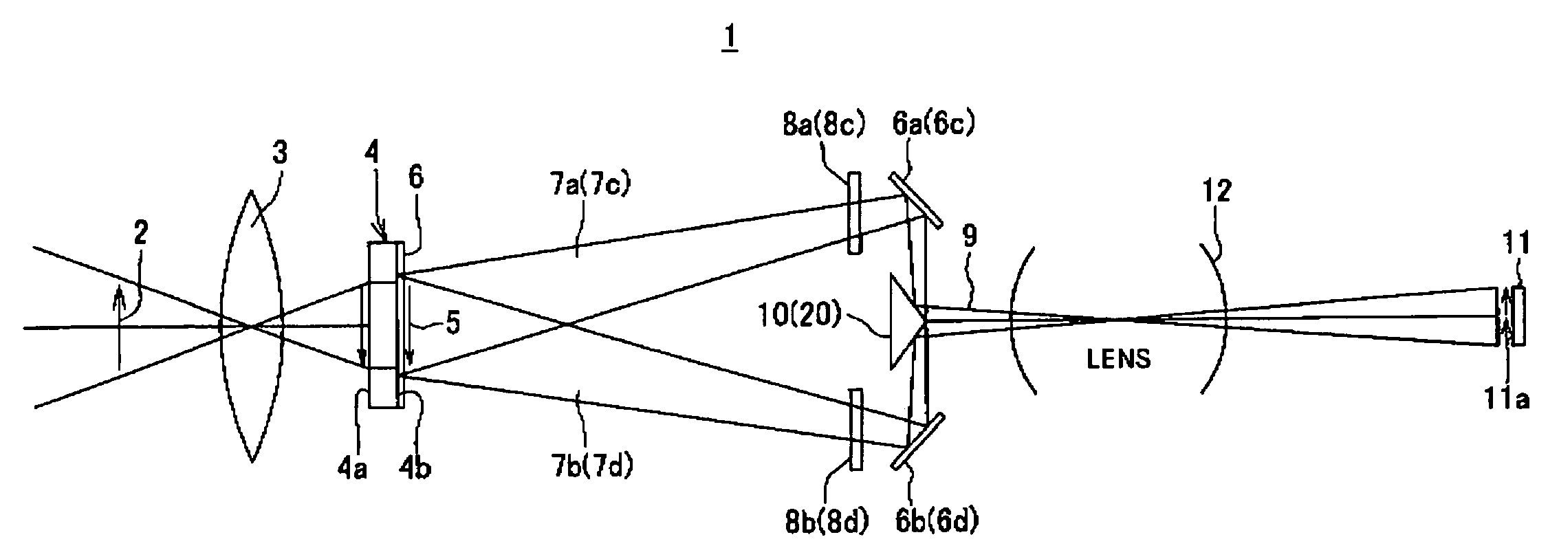
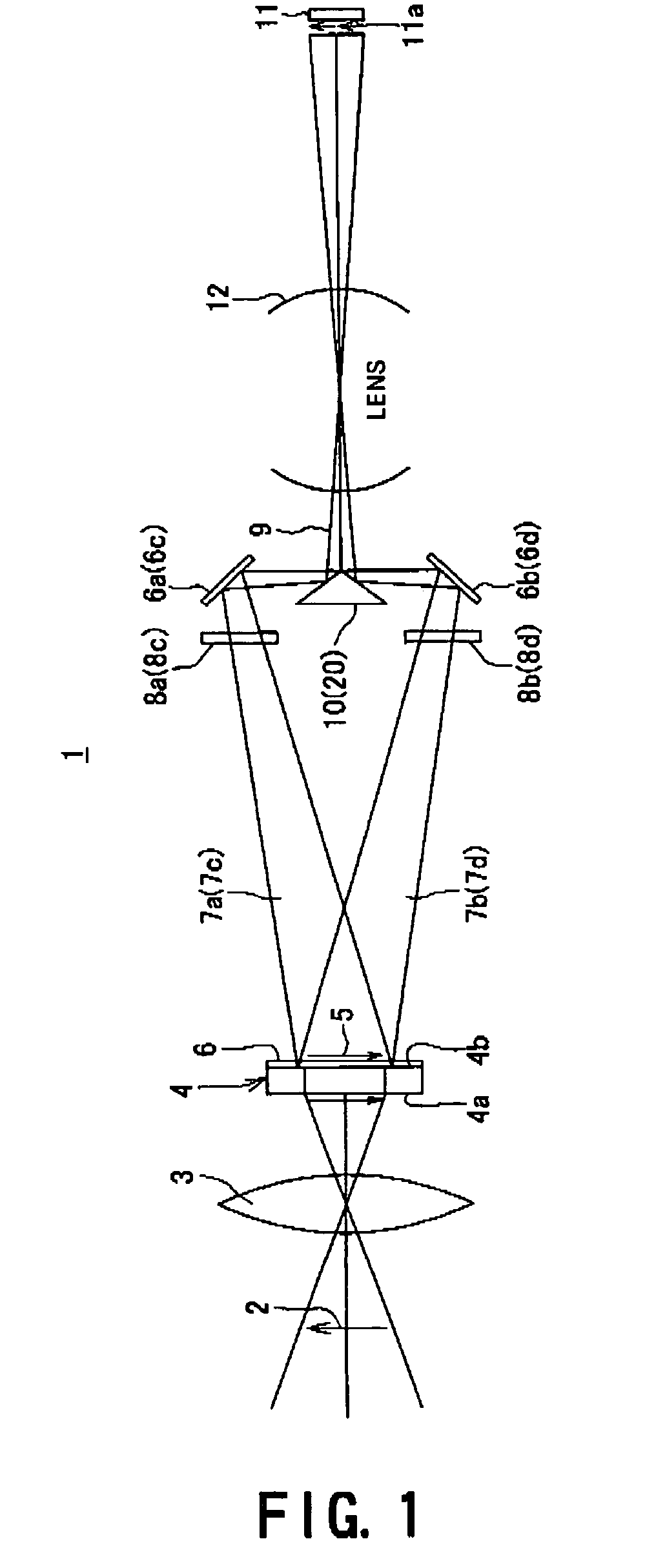
[0043]FIG. 1 is a schematic descriptive view illustrating the whole structure of a split-screen (or multi-split-screen) spectroscopic imaging apparatus 1 according to the first embodiment of the present invention. The split-screen spectroscopic imaging apparatus 1 is provided with an objective lens 3, which is disposed so as to be optically directed to a photogenic subject 2, and a fiber-optic plate 4 having a light-receiving end surface 4 on which an image of the photogenic subject 2 is to be primarily focused through the above-mentioned objective lens 3, and a light-emitting end surface 4b to which the primary imaging from the light-receiving end surface 4a to be transmitted. The fiber-optic plate 4 and the objective lens 3 form a primary imaging device. Even in case whe...


PUM


Abstract

A split-screen spectroscopic imaging apparatus including a fiber optic plate having a light receiving end face on which the photogenic subject is primarily focused by an objective lens and a light emitting end face to which the primarily focused image is transmitted. Total reflection mirrors optically separate the optical path of the image from the light emitting end face into a plurality of optical paths. Coherent filters optically separate the images of the optical paths separated by the total reflection mirrors into images of a plurality of wavelength bands. A two-slop reflection rectangular prism synthesizes the images separated by the coherent filters into a single image by arranging them in a predetermined direction. A reducing optical system optically reduces the magnification of the image from the two-slop reflection rectangular prism. And, a CCD imaging element images the images from the reducing optical system substantially simultaneously by a single imaging face.

Description

TECHNICAL FIELD[0001]The present invention relates to a split-screen (or multi-split-screen) spectroscopic imaging apparatus, which receives light from a photogenic subject of an optional or desired phenomenon such as combustion to separate optically the light into a plurality of images having frequency bands and performs imaging of these images on a single display screen so that these images are simultaneously displayed on the single display screen, and especially relates to such a split-screen spectroscopic imaging apparatus that permits to avoid parallax and improve a monitor displaying accuracy.BACKGROUND OF THE INVENTION[0002]In combustion of fuel in an internal combustion engine, a blue flame, which is caused upon ignition by means of an ignition plug, usually converts into a red flame, which is caused upon combustion or the other colored flame. With respect to a measure to conduct analysis of a fuel combustion phenomenon in such an internal combustion engine, analysis of temp...

Claims


Application Information

Patent Timeline
Patent Type & Authority Patents(United States)
IPC IPC(8): G01J3/51G01J3/30G01J3/36G01J3/28H04N5/225G01J3/02G01J3/00F02D45/00G03B11/00G03B15/00G03B17/17H04N9/07H04N13/02
CPCG01J3/02G01J3/0218G01J3/2823G01J3/36G01J3/51G01J3/513H04N5/2254
Inventor NAGASE, TOMOHIKOOONO, YOSHIO
Owner PHOTRON
Why Eureka
Try Eureka