Image coding apparatus and method

a compression technology and image coding technology, applied in the field of compression technology for image data, can solve the problems of inability to get proper evaluation of image quality from the user's point of view, inability to detect the degradation of image quality in many cases, and inability to achieve the effect of suppressing the variation of image quality

Active Publication Date: 2005-11-22
FUJIFILM BUSINESS INNOVATION CORP
View PDF13 Cites 9 Cited by
  • Summary
  • Abstract
  • Description
  • Claims
  • Application Information

AI Technical Summary

Benefits of technology

[0016]The present invention has been made in view of above circumstances and it is an object of the present invention t

Problems solved by technology

More particularly, if the resolution is lower, the degradation of the image quality is more conspicuous in many cases.
First, since normally a large number of images must be employed in the sensory evaluation by assigning a number of parameters, a great deal of time and labor are needed.
Third, if subjectivity of the evaluator is different from subjectivity of the actual user of the system, it is impossible to get proper evaluation of the image quality from the user's point of view.
Second, even if the input

Method used


Image

  • Image coding apparatus and method
  • Image coding apparatus and method
  • Image coding apparatus and method

Examples


first embodiment

[First Embodiment]

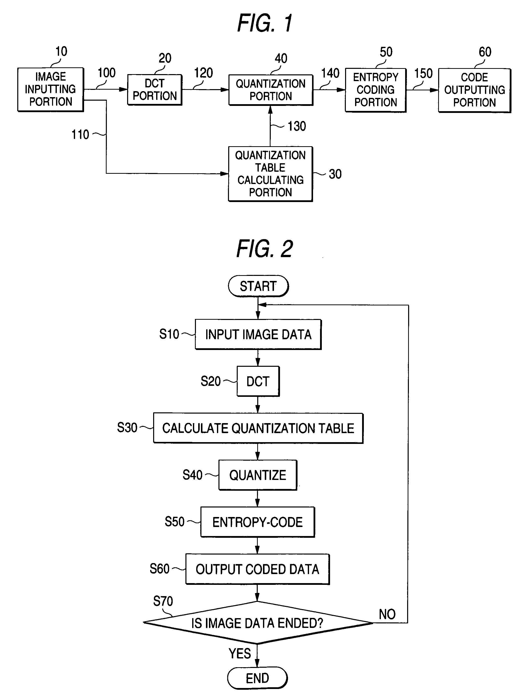
[0097]As a first embodiment of the invention, the example in which the invention is applied to JPEG will be explained. FIG. 1 is a block diagram showing the image coding apparatus according to the first embodiment. In FIG. 1, the same symbols are assigned to portions similar to those in FIG. 11, and their explanation will be omitted. Numeral 30 denotes a quantization table calculating portion.

[0098]Each of portions in FIG. 1 will be explained. The quantization table calculating portion 30 calculates the quantization table by a predetermined method based on the resolution data 110, and then supplies the calculated data to the quantizing portion 40 as the quantization table data 130.

[0099]An operation of the first embodiment will be explained based on the above configuration. FIG. 2 is a flowchart showing a coding operation of the first embodiment. In FIG. 2, the same symbols are assigned to portions similar to those in FIG. 11, and their explanation will be omitted....

second embodiment

[Second Embodiment]

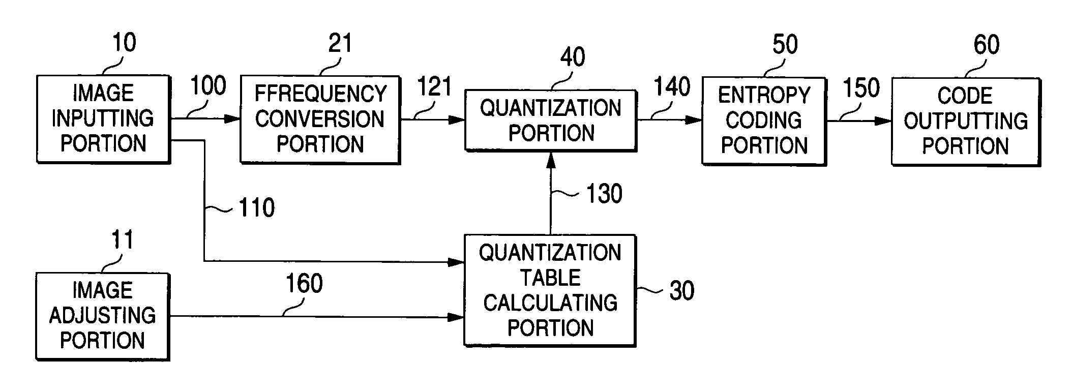
[0118]As a second embodiment of the present invention, an example in which the first embodiment is applied to the more common frequency conversion coding will be explained. Detailed explanation of the second embodiment will be given hereunder. FIG. 8 is an image coding apparatus of the second embodiment. In FIG. 8, the same numerals are assigned to the portions similar to those in FIG. 1 and FIG. 11, and their explanation will be omitted. Reference numeral 21 is a frequency converting portion, and 121 is frequency component data.

[0119]In the second embodiment, as shown in FIG. 8, the frequency converting portion 21 applies the frequency conversion to the image data 100 by a predetermined approach, and then sends out the data to the quantizing portion 40 as the frequency component data 121. Since an operation of the second embodiment based on the above configuration is apparent from the explanation in the first embodiment, their explanation will be omitted.

[0120]Th...

third embodiment

[Third Embodiment]

[0123]As a third embodiment of the present invention, an example in which the fine adjustment of the image quality is carried out will be explained. As has already been described, one of the problems in the related art is that, since the adjustment of the image quality is executed based on only stored results of the sensory evaluations, it is impossible to executed the fine adjustment of the image quality. In this case, it is evident that, as has already been examined by Eq. (7), the present invention can correspond to the unexpected incomplete resolution. Therefore, the embodiment in which the fine adjustment of the image quality is applied will be explained hereunder.

[0124]There are various references of the image quality according to the user. For example, in the printer, the image quality offered by the designer is totally different from that requested by the normal office worker. In such case, it is preferable that the adjustment of the image quality should be...


PUM


Abstract

The image input from the image inputting portion 10 are DCT-converted by the DCT portion 20, then the converted result is quantized by the quantizing portion 40, then the quantized result is entropy-coded by the entropy coding portion 50, and then the coded output is output. The quantization table calculating portion 30 holds respective reference quantizing steps for the reference resolution, then receives the resolution data of the input image, then calculates respective quantizing steps based on (quantizing step)=(reference quantizing step)/(reference resolution)×(resolution of the input image) so as to fit to the input image, and then prepares the quantization table.

Description

BACKGROUND OF THE INVENTION[0001]1. Field of the Invention[0002]The present invention relates to the compression technology for image data and, more particularly, the lossy compressed coding for multi-level input image.[0003]2. Description of the Related Art[0004]Since normally image data have an enormous amount of data, in case of communication, store, and the like, the image data is compressed to reduce an amount of data. Coding approach of the image data is roughly classified into two types of a lossless coding system and a lossy coding system.[0005]As for the latter, for example, abase line system defined by Joint Photographic Experts Group (referred simply to as JPEG hereinafter) is a typical compression system (For example, Endo; “International Standard Coding System of Color Still Image” Interface, December 1991, pp.160–167). Normally the lossy compression can control tradeoff between image quality and an amount of codes by coding parameters. In JPEG, a quantization table cor...

Claims


Application Information

Patent Timeline
IPC IPC(8): G06T9/00H04N7/26H04N7/30H04N7/46H03M7/30H03M7/40H04N19/126H04N19/132H04N19/136H04N19/176H04N19/196H04N19/60H04N19/625H04N19/63H04N19/85H04N19/91
CPCH04N19/172H04N19/63H04N19/60H04N19/124H04N19/136H04N19/154H04N19/59
Inventor YOKOSE, TARO
Owner FUJIFILM BUSINESS INNOVATION CORP
Why Eureka
Try Eureka