Eureka AIR delivers breakthrough ideas for toughest innovation challenges, trusted by R&D personnel around the world.

H-bridge circuit for generating a high-energy biphasic and external pacing waveform in an external defibrillator

a high-energy biphasic and external pacing technology, applied in the field of generating defibrillator apparatus and pacing waveforms, can solve the problems that the circuitry used to generate pacing pulses cannot be used for generating defibrillator pulses, and is common and life-threatening medical conditions, so as to simplify the assembly and manufacturing of the defibrillator device. , the effect of simplifying the drive circuitry

Inactive Publication Date: 2005-11-22
PHYSIO CONTROL INC
View PDF57 Cites 22 Cited by
  • Summary
  • Abstract
  • Description
  • Claims
  • Application Information

AI Technical Summary

Benefits of technology

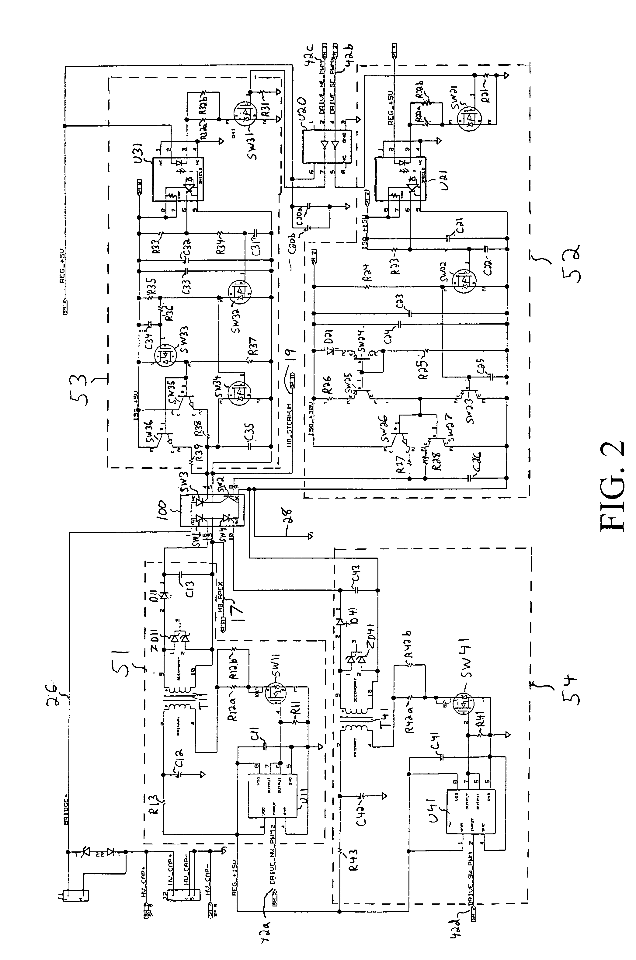
[0011]In accordance with another aspect of the invention, the pacing current is conducted through one of the SCRs of the H-bridge. A drive circuit for the SCR is derived such that the SCR may be continuously driven on for either a biphasic waveform pulse or a pace waveform pulse. The drive circuit is able to hold on the high power SCR at current levels well below the holding current levels of the SCR, such as may occur during pacing applications. Additionally, for delivering the high energy biphasic defibrillation waveform, the drive circuit has sufficient drive level to turn on the high power SCR for delivering the high energy defibrillation waveform. This topology is advantageous in that a single power switch can be utilized for generating the pace waveform pulse or the biphasic waveform pulse, thus reducing the total number of parts required to implement both biphasic and pacing waveform generation.
[0013]In accordance with still another aspect of the invention, a single power switch is utilized in each of the legs of the H-bridge output circuit, and are included in a single integrated module or package. The use of single semiconductor switches in an integrated surface mountable module or package simplifies the assembly and manufacturing of the defibrillator device. The use of a single IGBT in a leg of the H-bridge (as opposed to two or more IGBTs in series) also greatly simplifies the drive circuitry required to turn on and off the IGBT.

Problems solved by technology

One of the most common and life-threatening medical conditions is ventricular fibrillation, a condition where the human heart is unable to pump the volume of blood required by the human body.
For example, each pacing pulse typically has an energy of about 0.05 J to 1.2 J. Because of the small energies used for pacing pulses, the circuitry used to generate the pacing pulses cannot typically be used for generating defibrillation pulses, which are typically of much higher energies and currents.
Of course, having separate defibrillation and pacing circuits tends to increase the cost and size of the unit.
In addition, because implantable defibrillators and pacers typically apply relatively low energy pulses, the output circuitry for such implantable units is generally not adaptable for use in an external unit.

Method used


Image

  • H-bridge circuit for generating a high-energy biphasic and external pacing waveform in an external defibrillator
  • H-bridge circuit for generating a high-energy biphasic and external pacing waveform in an external defibrillator
  • H-bridge circuit for generating a high-energy biphasic and external pacing waveform in an external defibrillator

Examples


Embodiment Construction

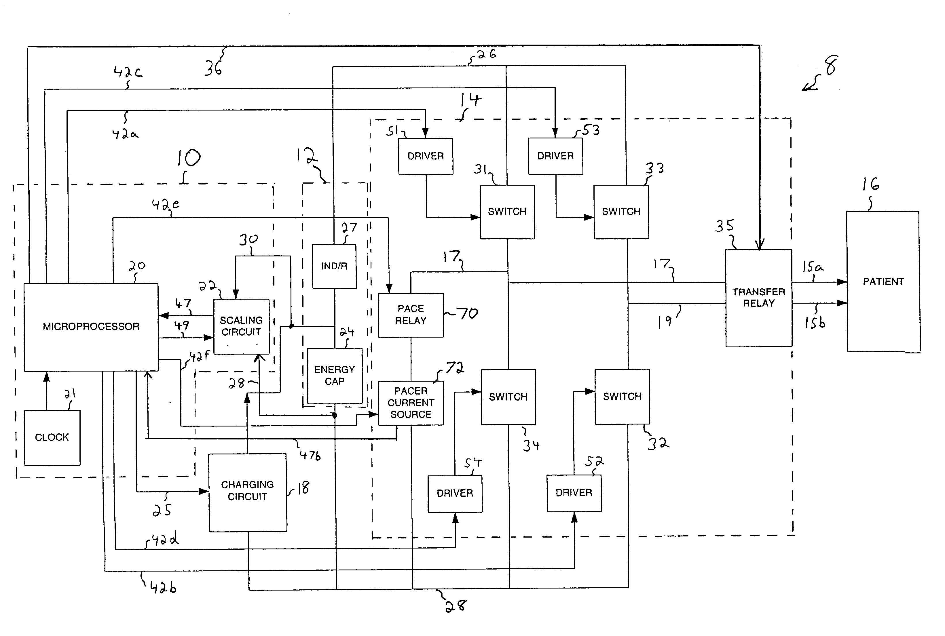
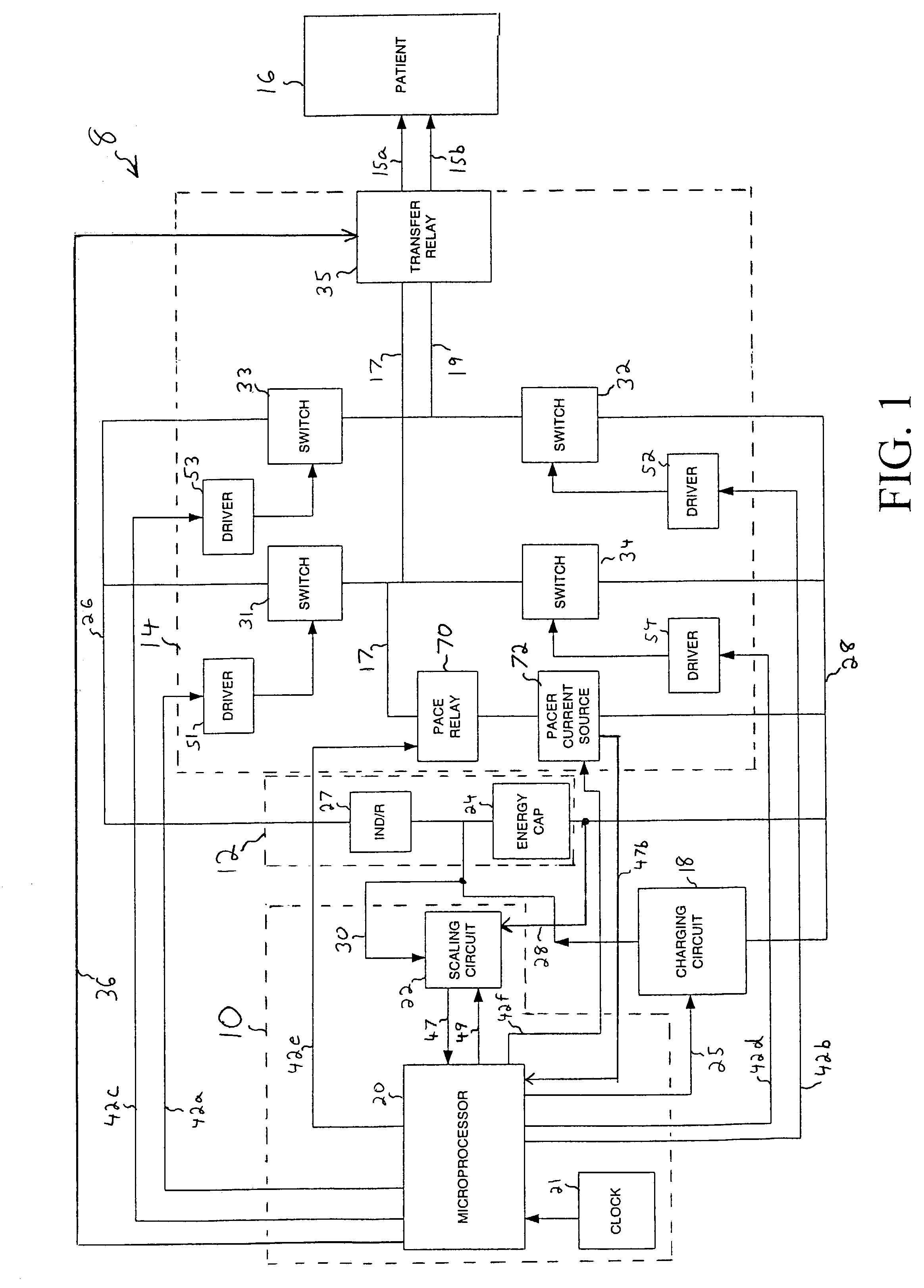
[0022]FIG. 1 is a block diagram illustrative of an external combined defibrillator / pacer 8, according to one embodiment of the present invention. The defibrillator / pacer 8 is connected to a patient 16 and includes a microprocessor 20 that is connected to an energy storage capacitor 24 via a charging circuit 18. It will be appreciated by those skilled in the art that energy storage capacitor 24 may be implemented with a multi-capacitor network (i.e., with capacitors connected in series and / or parallel). During the operation of the defibrillator / pacer 8, microprocessor 20 controls charging circuit 18 using a signal on a control line 25 to charge energy storage capacitor 24 to a desired voltage level. To monitor the charging process, microprocessor 20 is connected to a scaling circuit 22 by a measurement line 47, and by a control line 49. It will be understood that while single measurement and control lines are shown, multiple lines may be used. Scaling circuit 22 is connected to energ...


PUM


Abstract

A circuit for generating both a biphasic defibrillation waveform and an external pacing waveform in an external defibrillator is provided. The output circuit of the device utilizes one or more SCR switches for applying energy to a patient. In one embodiment, the output circuit is in the form of an H-bridge, with three SCR legs and one IGBT leg. A drive circuit for one of the SCR legs is provided such that the SCR may be continuously driven on for either a high energy biphasic defibrillation pulse or a low energy pacing pulse. In one embodiment, the output circuit conducts the pacing waveform through a combination of one upper leg SCR of the H-bridge and a current source. The current source is configured to bypass a lower leg SCR of the H-bridge. The output circuit is capable of conducting pacing currents of as low as 10 mA. The output circuit is also capable of conducting a high energy biphasic defibrillation waveform of as high as 200 or more joules, and also a low energy defibrillation pulse of as low as 1 to 50 joules. The output circuit is also capable of conducting currents as high as approximately 200 amperes.

Description

FIELD OF THE INVENTION[0001]This invention relates generally to apparatus for generating defibrillation and pacing waveforms, and more particularly to a circuit for generating a high-energy biphasic and external pacing waveform in an external defibrillator.BACKGROUND OF THE INVENTION[0002]One of the most common and life-threatening medical conditions is ventricular fibrillation, a condition where the human heart is unable to pump the volume of blood required by the human body. The generally accepted technique for restoring a normal rhythm to a heart experiencing ventricular fibrillation is to apply a strong electric pulse to the heart using an external cardiac defibrillator. External cardiac defibrillators have been successfully used for many years in hospitals by doctors and nurses, and in the field by emergency treatment personnel, e.g., paramedics.[0003]Conventional external cardiac defibrillators first accumulate a high-energy electric charge on an energy storage capacitor. When...

Claims


Application Information

Patent Timeline
Patent Type & Authority Patents(United States)
IPC IPC(8): A61N1/39
CPCA61N1/3906A61N1/3968A61N1/3975
Inventor WALTMAN, BARRY F.
Owner PHYSIO CONTROL INC
Why Eureka
Eureka Blog
Learn More