Device and method for controlling the position for working devices of mobile machines

a technology of mobile machines and working devices, which is applied in the direction of mechanical machines/dredgers, door/window fittings, non-denominational number representation computation, etc., can solve the problems of insufficient one-dimensional level correction and one-dimensional orientation of the level-regulating device known from de 39 38 766 a1

Inactive Publication Date: 2005-11-22
HYDROMATIK GMBH
View PDF19 Cites 27 Cited by
  • Summary
  • Abstract
  • Description
  • Claims
  • Application Information

AI Technical Summary

Benefits of technology

[0008]Accordingly, the objective of the present invention is to propose a device and a method for regulating the position of working mechanisms of mobile machines, by means of which the working mechanism

Problems solved by technology

One particular disadvantage of the level-regulating device known from DE 39 38 766 A1 is the one-dimensional orientation.
In the embodiment described as an example in the above-mentioned patent specification of providing a levelling means on a loading and unloading cr

Method used


Image

  • Device and method for controlling the position for working devices of mobile machines
  • Device and method for controlling the position for working devices of mobile machines
  • Device and method for controlling the position for working devices of mobile machines

Examples


first embodiment

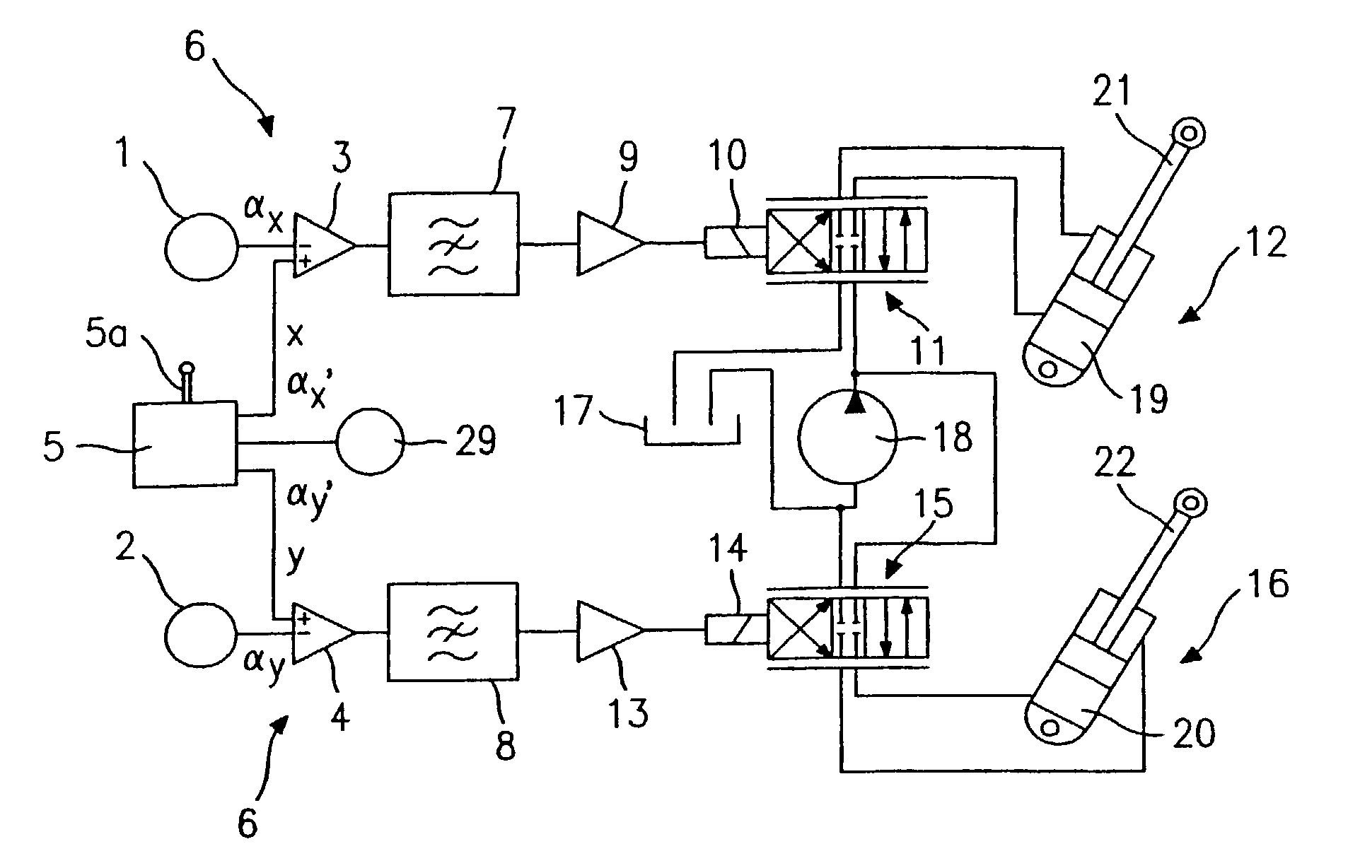
[0023]FIG. 1 is a first circuit diagram of the position-regulating device proposed by the invention for working mechanisms of mobile machines. The circuit has a first sensor 1, which measures a first angle in a first spatial direction, hereafter denoted by x. This first angle will be referred to hereafter as αx. Similarly, a second sensor 2 measures a second angle in a second spatial direction y. The second angle is referred to hereafter as αy. The measured angles αx and αy are compared by means of a first comparator 3 and a second comparator 4 with an angle αx′ for the spatial direction x and αy′ for the spatial direction y fixed by an angle detector 5, which may be 90° respectively, for example. The comparators 3 and 4 form a comparator unit 6. The angle detector 5 may provide either a fixed, predetermined or manually variable angle αx′ or αy′ using manually controlled detector 5a.

[0024]After the first comparator 3, the signal in x-direction is run through a first band-stop filte...

second embodiment

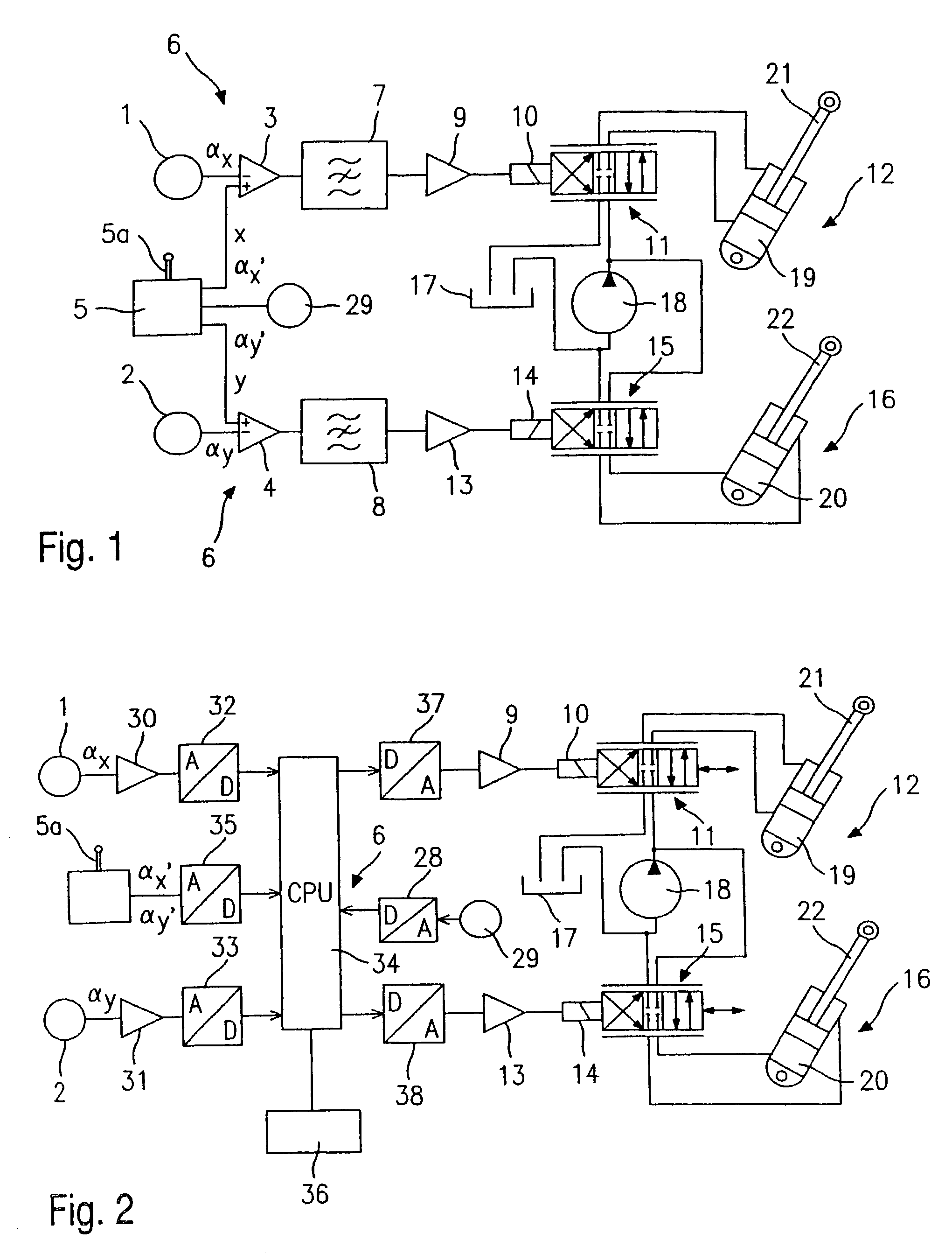
[0029]FIG. 2 illustrates a position-regulating device proposed by the invention for working mechanisms of mobile machines. The same reference numbers are used for components described with reference to FIG. 1 and will not be described again below. Whilst the embodiment of FIG. 1 is built using analogue technology, the embodiment illustrated in FIG. 2 is based on digital technology.

[0030]The device illustrated in FIG. 2 primarily differs from the device shown in FIG. 1 due to the use of a digital control unit 34, which assumes the function both of the band-stop filters 7 and 8 and the comparator unit 6.

[0031]Accordingly, the comparator unit 6 is built as follows. The angle αx emitted by the sensor 1 is pre-amplified in a first pre-amplifier 30 and then converted by a first analogue-to-digital converter 32 from an angular value measured in analogue to a digital value that can be processed by a digital control unit 34. Similarly, the angle αy is amplified by a second pre-amplifier 31 a...


PUM


Abstract

The invention relates to a device for controlling the position for work devices (41) of mobile machines (40). The inventive device comprises a measuring device (1,2) for measuring an angle (α) which is formed between a level (42) that is determined by the position of the work device (41) and the direction of the gravitational force (g). The inventive device also comprises an angle transmitter (5) for predetermining an angle (α′) which is formed between a level (42) that is determined by the position of the work device (41) and the direction of the gravitational force (g). The inventive device further comprises a controller (3, 4, 6–16) for controlling the angle (α) between the level (42) of the work device (41) and the direction of the gravitational force (g) in such a way that the measured angle (α) matches the predetermined angle (α′).

Description

BACKGROUND OF THE INVENTION[0001]1. Field of the Invention[0002]The invention relates to a position-regulating device for working mechanisms of mobile machines and a method of regulating the position of working mechanisms of mobile machines.[0003]2. Discussion of the Prior Art[0004]A micro-mechanical incline sensor, in particular for motor vehicles, is known as such from DE 197 52 439 A1, and has a bearing plate, the inclination of which is determined relative to the horizontal. At least two pressure sensor units are integrated on the bearing plate to determine a pressure applied to the plate at the respective points. An earth plate is connected to the bearing plate via the pressure sensor units. An evaluation unit uses the data produced by the pressure sensor units to determine the inclination of the bearing plate relative to the horizontal. Depending on the inclination of the device in which the inclination sensor is integrated, the earth plate applies a different degree of force ...

Claims


Application Information

Patent Timeline
IPC IPC(8): E02F3/43
CPCE02F3/432E02F3/433
Inventor VONNOE, REINHARDBRAND, MICHAEL
Owner HYDROMATIK GMBH
Why Eureka
Try Eureka