Temperature controlled shipping containers

a technology for shipping containers and cooling devices, applied in domestic cooling devices, cooling methods, containers, etc., can solve the problems of large volume of ice/gel packs, hazardous dry ice, and inability to accept air freight, etc., to enhance the cooling capability of sorption cooling devices, improve thermal conductivity, and improve the effect of thermal conductivity

Inactive Publication Date: 2005-11-29
PELICAN NANOCOOL HLDG LLC
View PDF35 Cites 69 Cited by
  • Summary
  • Abstract
  • Description
  • Claims
  • Application Information

AI Technical Summary

Benefits of technology

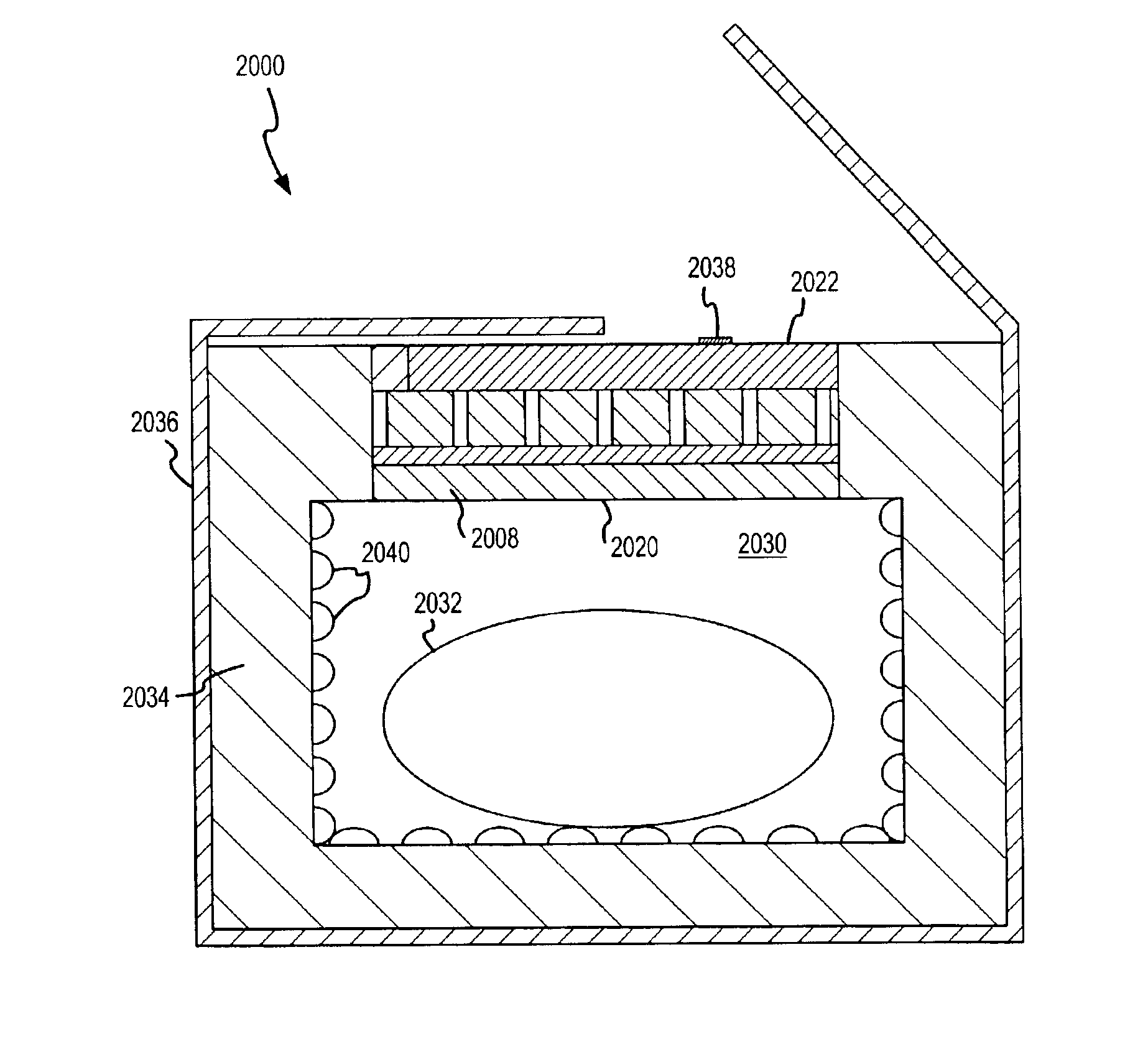
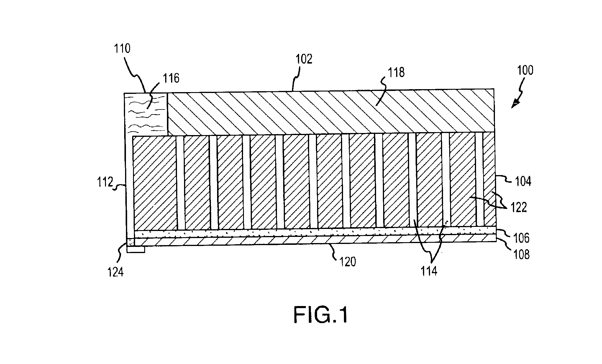
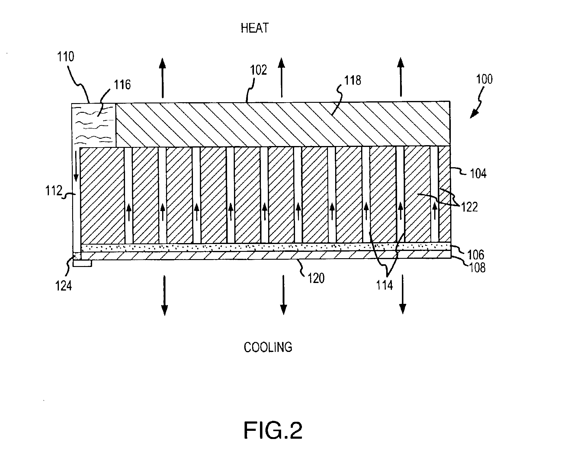
[0021]According to another embodiment of the present invention, a sorption cooling device is provided that includes an evaporator for providing cooling, an absorber adapted to absorb vapor formed in the evaporator and vapor passageway adapted to permit vapor flow from the evaporator to the absorber. The vapor passageway includes a thermally insulating material heading a thermal resistance of at least about 2.8 K·m2 / W. Accordingly, heat generated in the absorber is thermally isolated from the evaporator, enhancing the cooling capability of the sorption cooling device.
[0022]According to another embodiment of the present invention, a sorption cooling device is provided including an evaporator having a cooling surface, an absorber adapted to absorb vapor formed in the evaporator and a vapor passageway disposed between the evaporator and absorber. The absorber includes a desiccant and a thermally conductive material disposed within the desiccant, wherein the thermally conductive material has a higher thermal conductivity than the desiccant. The higher thermal conductivity material enhances the ability of the absorber to transfer heat away from the evaporator, thereby enhancing the cooling ability of the sorption cooling device.

Problems solved by technology

Therefore, a large mass and volume of the ice / gel packs is required to cool the shipping container.
Although dry ice has a higher energy density, dry ice is considered hazardous and is not an acceptable material for air freight.

Method used


Image

  • Temperature controlled shipping containers
  • Temperature controlled shipping containers
  • Temperature controlled shipping containers

Examples


example 1

Cooling Device with Extended Cooling Time

[0224]Example 1 was a Size A cooling device with 400 grams of desiccant and 200 milliliters of water in the slow feed water reservoir. This cooling device also had two layers of wicking material, instead of one. The cooling device was tested in a VIP container and the results are illustrated in FIG. 28, which shows the ambient temperature, desiccant temperature and internal base temperature as a function of time.

[0225]As is illustrated in FIG. 28, the temperature of the cavity dropped from about 26° C. to about 6° C. and the temperature did not rise above 10° C. for at least 48 hours.

example 2

Effect of Starter Reservoir on Performance

[0226]Two Size A cooling devices (Examples 2A and 2B) were assembled so that they were identical to each other except that Example 2A did not have a starter liquid reservoir and Example 2B utilized a starter reservoir. Both were tested in VIP containers. The results for Example 2A are illustrated in FIG. 29 and the results for Example 2B are illustrated in FIG. 30. It can be seen that the internal cavity of Example 2B exhibited a rapid drop to less than 5° C., whereas the internal cavity of Example 2A dropped to slightly less than 10° C., demonstrating the effectiveness of utilizing a starter liquid reservoir.

example 3

EPS Container vs. VIP Container

[0227]Two identical Size A cooling devices were assembled. One (Example 3A) was tested in an EPS container and the other (Example 3B) was tested in a VIP container. The results for Example 3B are illustrated in FIG. 31 and the results for Example 3A are illustrated in FIG. 32.

[0228]As expected, the VIP container yielded a reduced internal cavity temperature over a longer period of time due to the improved thermal insulation properties of the VIPs.


PUM

PropertyMeasurementUnit
temperatureaaaaaaaaaa
pressureaaaaaaaaaa
pressureaaaaaaaaaa

Abstract

Novel sorption cooling devices capable of providing cooling over an extended period of time are disclosed. The sorption cooling devices are particularly useful for temperature-controlled shipping containers that are required to maintain a temperature below ambient for a time sufficient to complete delivery of the container and its contents. The shipping containers can be utilized to cost-effectively transport temperature-sensitive products.

Description

CROSS-REFERENCE TO RELATED APPLICATIONS[0001]This application claims priority and is a continuation in part to U.S. patent application Ser. No. 09 / 876,841 filed Jun. 6, 2001 now U.S. Pat. No. 6,584,797 and U.S. patent application Ser. No. 09 / 970,094 filed Oct. 2, 2001 now U.S. Pat. No. 6,688,132. Each of these U.S. Patent Applications is incorporated herein by reference in its entirety.BACKGROUND OF THE INVENTION[0002]1. Field of the Invention[0003]The present invention is directed to improved sorption cooling devices and methods for using sorption cooling devices. In particular, the present invention is directed to sorption cooling devices that are particularly adapted to maintain a reduced temperature within an enclosed container for an extended period of time. The cooling devices are particularly useful for temperature-controlled shipping containers that must maintain a temperature below ambient for extended time periods, such as from 1 hour to about 120 hours, or more.[0004]2. D...

Claims


Application Information

Patent Timeline
Patent Type & Authority Patents(United States)
IPC IPC(8): F25D9/00C09K5/04F25B17/02F25B17/08F25D11/00
CPCC09K5/047F25B17/02F25B17/08F25D11/003F25D2201/126F25D2201/14F25D2331/804Y02B40/34Y02B40/00
Inventor SMITH, DOUGLAS M.O'BRIEN, TAMARA L.RODERICK, KEVIN H.WARREN, LOIS X.PERKES, RICHARD G.SINCLAIR, VANESSASHRIMPTON, QUENTIN
Owner PELICAN NANOCOOL HLDG LLC
Why Eureka
Try Eureka