
Hydrate-based desalination with hydrate-elevating density-driven circulation

a technology of density-driven circulation and desalination, which is applied in the direction of vacuum distillation separation, separation process, vessel construction, etc., to achieve the effect of increasing the rate at which hydrates, improving heat dissipation, and more hydrates

Inactive Publication Date: 2005-11-29
WATER REGENERATION SYST
View PDF93 Cites 27 Cited by
  • Summary
  • Abstract
  • Description
  • Claims
  • Application Information

AI Technical Summary

Benefits of technology

This approach significantly increases the rate of hydrate rise to the dissociation region, reduces gas infusion, and minimizes mixing with seawater, resulting in improved fresh water percentage yield and purity.

Problems solved by technology

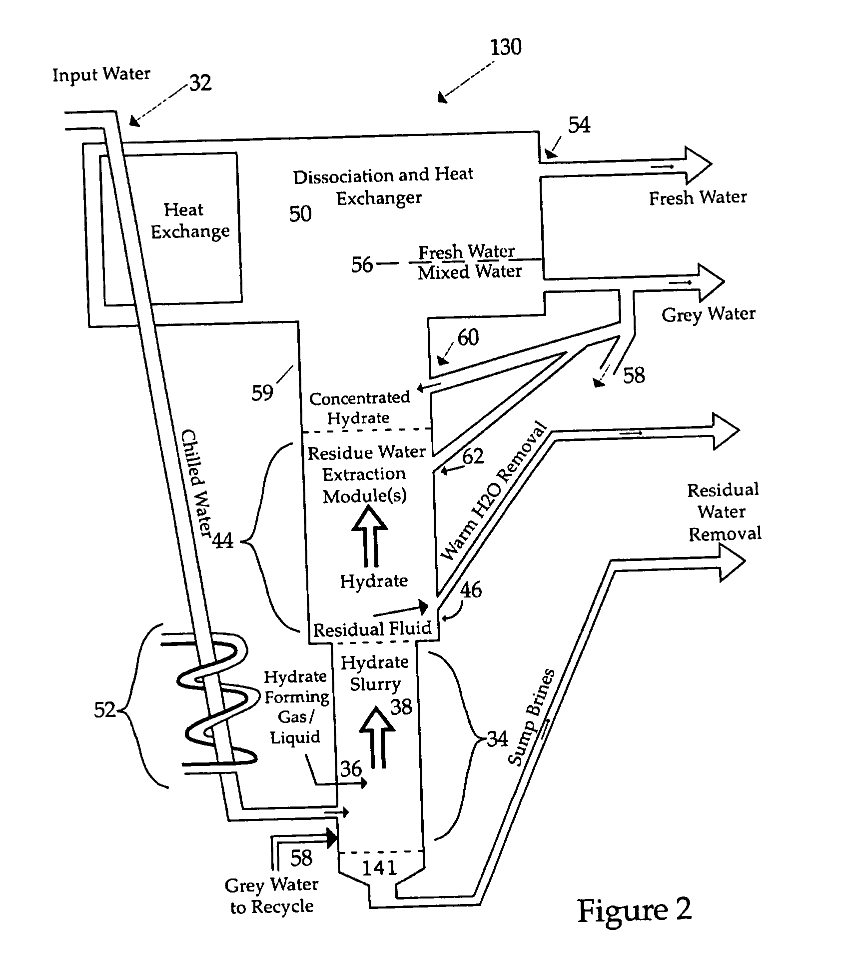
As the hydrate rises, it becomes unstable and disassociates into pure water and the hydrate-forming gas or gas mixture.

Method used


Image

  • Hydrate-based desalination with hydrate-elevating density-driven circulation
  • Hydrate-based desalination with hydrate-elevating density-driven circulation
  • Hydrate-based desalination with hydrate-elevating density-driven circulation

Examples


Embodiment Construction

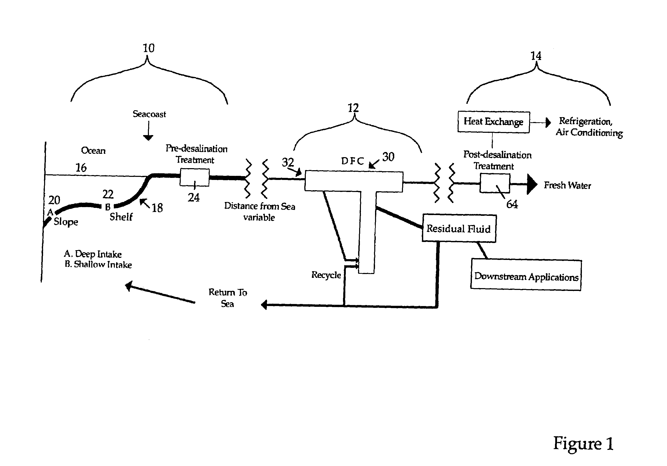
[0025]A land-based desalination installation is shown schematically in FIG. 1 in generalized fashion. The installation may be divided roughly into three sections or regions: an intake portion 10; a water purification portion 12; and post-processing and downstream usage section 14.

[0026]The intake portion 10 consists essentially of the apparatus and various subinstallations necessary to extract seawater from the ocean 16 and transport it to the desalination / purification installation at region 12, including subaquatic water intake piping 18 and pumping means (not shown) to draw the water from the ocean and pump it to shore for subsequent processing. Large volume installations can be located relatively close to the sea to reduce the piping distance of the input water to a minimum, and establishing the installation as close to sea level as possible will reduce the cost of pumping against pressure head.

[0027]The intake pipeline 18 preferably extends sufficiently out to sea that it draws ...


PUM

PropertyMeasurementUnit
diameteraaaaaaaaaa
depthaaaaaaaaaa
temperatureaaaaaaaaaa

Abstract

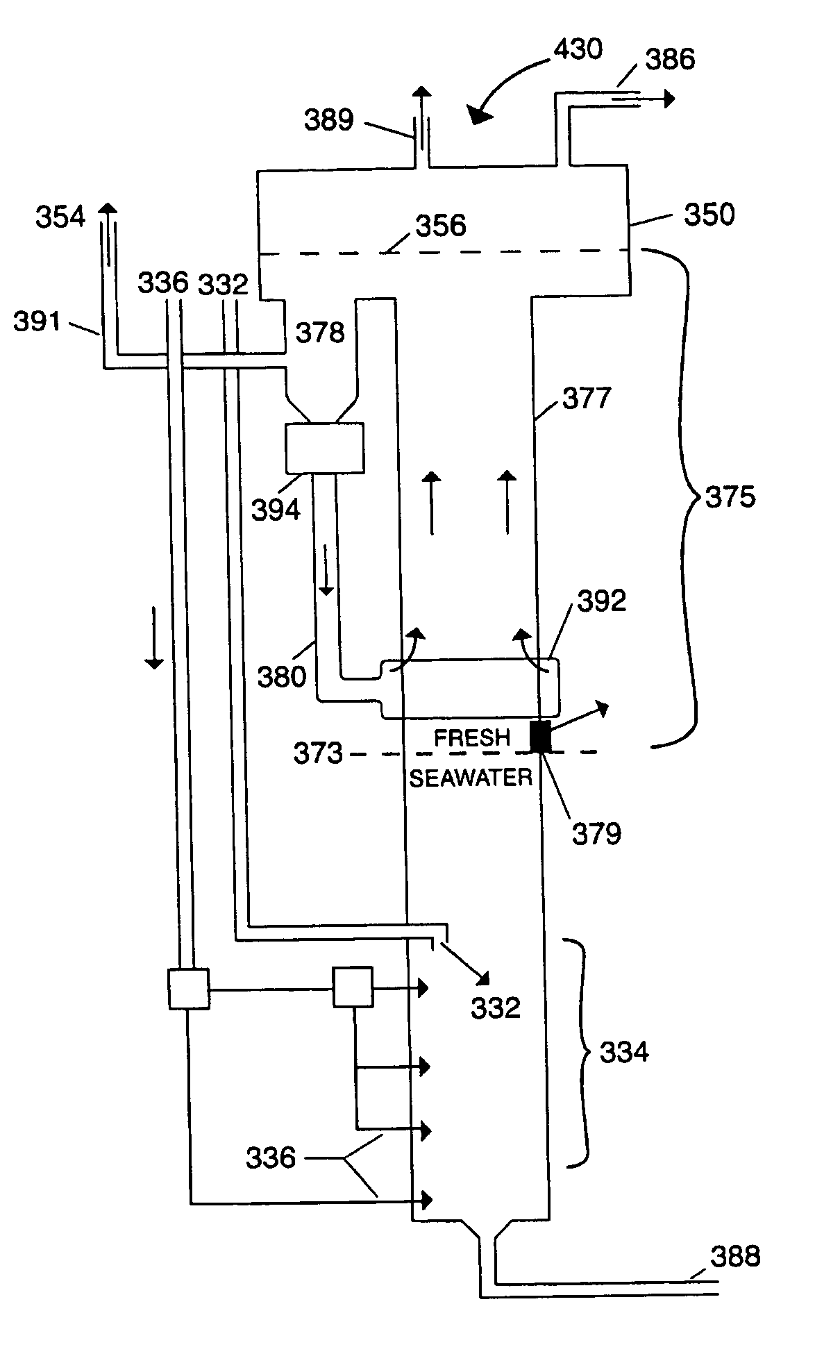
In hydrate-based desalination or other water purification conducted using naturally buoyant or trapped-gas-assisted buoyancy hydrate in a hydrate fractionation column, a portion of fresh or purified product water is extracted from an upper, hydrate dissociation region of the fractionation column and reintroduced into a lower portion of the fractionation column at a point above but generally near a product water / saline water interface. The difference in density between the reintroduced product water and the fluid in the hydrate fractionation column above the point of reintroduction (water, hydrate, and gas) drives a natural circulation system which enhances the rate at which hydrate rises into the hydrate dissociation region.

Description

CROSS-REFERENCE TO RELATED APPLICATIONS[0001]This application is a continuation-in-part of U.S. patent application Ser. No. 10 / 266,258 filed Oct. 8, 2002, (now issued as U.S. Pat. No. 6,733,667 May 11, 2004), which is a divisional of U.S. patent application Ser. No. 09 / 397,500 filed Sep. 17, 1999 (now issued as U.S. Pat. No. 6,497,794 on Dec. 24, 2002), which is a continuation-in-part of U.S. patent application Ser. No. 09 / 375,410 filed Aug. 17, 1999 (now issued as U.S. Pat. No. 6,531,034 on Mar. 11, 2003), which is a continuation-in-part of U.S. patent application Ser. No. 09 / 350,906 filed on Jul. 12, 1999 (now issued as U.S. Pat. No. 6,565,715 on May 20, 2003), the entire contents of all four of which are incorporated by reference. Priority is claimed from each of those four applications.[0002]This application is also a continuation-in-part of U.S. patent application Ser. No. 09 / 941,545 filed Aug. 30, 2001, (now U.S. Pat. No. 6,767,471 on Jul. 27, 2004), which is based on now-expi...

Claims


Application Information

Patent Timeline
Patent Type & Authority Patents(United States)
IPC IPC(8): C02F1/00C02F1/04C02F1/22
CPCC02F1/22C02F1/26C02F2103/08Y02A20/124
Inventor MAX, MICHAEL D.KORSGAARD, JENS
Owner WATER REGENERATION SYST
Learn More