Hybrid inductive sensor

a technology of inductive sensor and hybrid induction sensor, which is applied in the direction of instruments, devices using electric/magnetic means, and magnetic field measurement using permanent magnets. it can solve the problem of imposing a cost of 50 to 100 man-hours per fligh

Inactive Publication Date: 2005-11-29
THE BOEING CO
View PDF2 Cites 15 Cited by
  • Summary
  • Abstract
  • Description
  • Claims
  • Application Information

AI Technical Summary

Benefits of technology

[0008]A variable reluctance sensor with an excitation apparatus added to the sensor coil benefits from the tried and tested reliability of a variable reluctance sensor while introducing the accurate low speed measurement of a variable inductance sensor. If the variable inductance circuit fails, the variable reluctance speed sensor remains capable of accurately functioning. Therefore, the capabilities of a variable inductance sensor can be incorporated without the risks associated with a device that has no history of manned space flight use.
[0009]Additional benefits of a hybrid sensor include, a signal at speeds approaching zero, a usable signal from smooth targets, greater detection range through metal housings and over moderate gaps and signal amplitude that is not speed dependent. In the case of a hybrid sensor that incorporates a magnet on the target, this extends the additional benefits beyond moderate gaps to large gaps.
[0010]A hybrid sensor according to the present disclosure may reduce or eliminate the cost and schedule impact associated with between-flight Space Shuttle Main Engine (SSME) removal and torque checks. Between-flight torque checks of the SSME pumps may impose a cost of 50 to 100 man-hours per flight. The SSME heat shields must be removed prior to performing the torque checks on its pumps. Heat shield removal is one of several other torque-check associated costs. Additionally, if heat shields can be left on between flights, this is one step toward leaving the engines in the space shuttle between flights generating the potential for further indirect savings. A hybrid sensor may realize at least 50 to 100 man-hours savings in turnaround time per flight and in the best scenario it may facilitate turnaround of the space shuttle without SSME removal. This would lead to a reduction in parts and processes associated with engine removal such as seals, fasteners, soap solution, tools, and paperwork. Also, the incorporation of the hybrid sensor technology will allow detection of an anomalous run torque within 2 hours after Main Engine Cutoff (MECO). Therefore, even if the between-flight SSME removal and torque checks are not eliminated, pump diagnosis and maintenance strategy can occur long before the shuttle returns to the ground. If the in-flight run torque proves trustworthy, there may be a reduction in orbiter processing and cycle time.
[0012]Excitation apparatus may be added to existing variable reluctance sensor designs without destroying the ability of the variable reluctance sensor to function as a variable reluctance sensor. Accordingly, the zero speed function associated with the variable inductance sensor can be obtained without compromising the reliability of the variable reluctance sensor. If the zero speed measurement circuit fails, the traditional variable reluctance function would still be present. This redundancy amounts to a significant reward with an insignificant risk.
[0013]Accordingly, the proximity sensing function associated with the variable inductance sensor can be obtained without compromising the reliability of the variable reluctance sensor. If the proximity sensing circuit fails, the traditional variable reluctance function would still be present. Again, this amounts to a significant gain without a significant risk.

Problems solved by technology

Between-flight torque checks of the SSME pumps may impose a cost of 50 to 100 man-hours per flight.
Heat shield removal is one of several other torque-check associated costs.

Method used


Image

  • Hybrid inductive sensor
  • Hybrid inductive sensor
  • Hybrid inductive sensor

Examples


Embodiment Construction

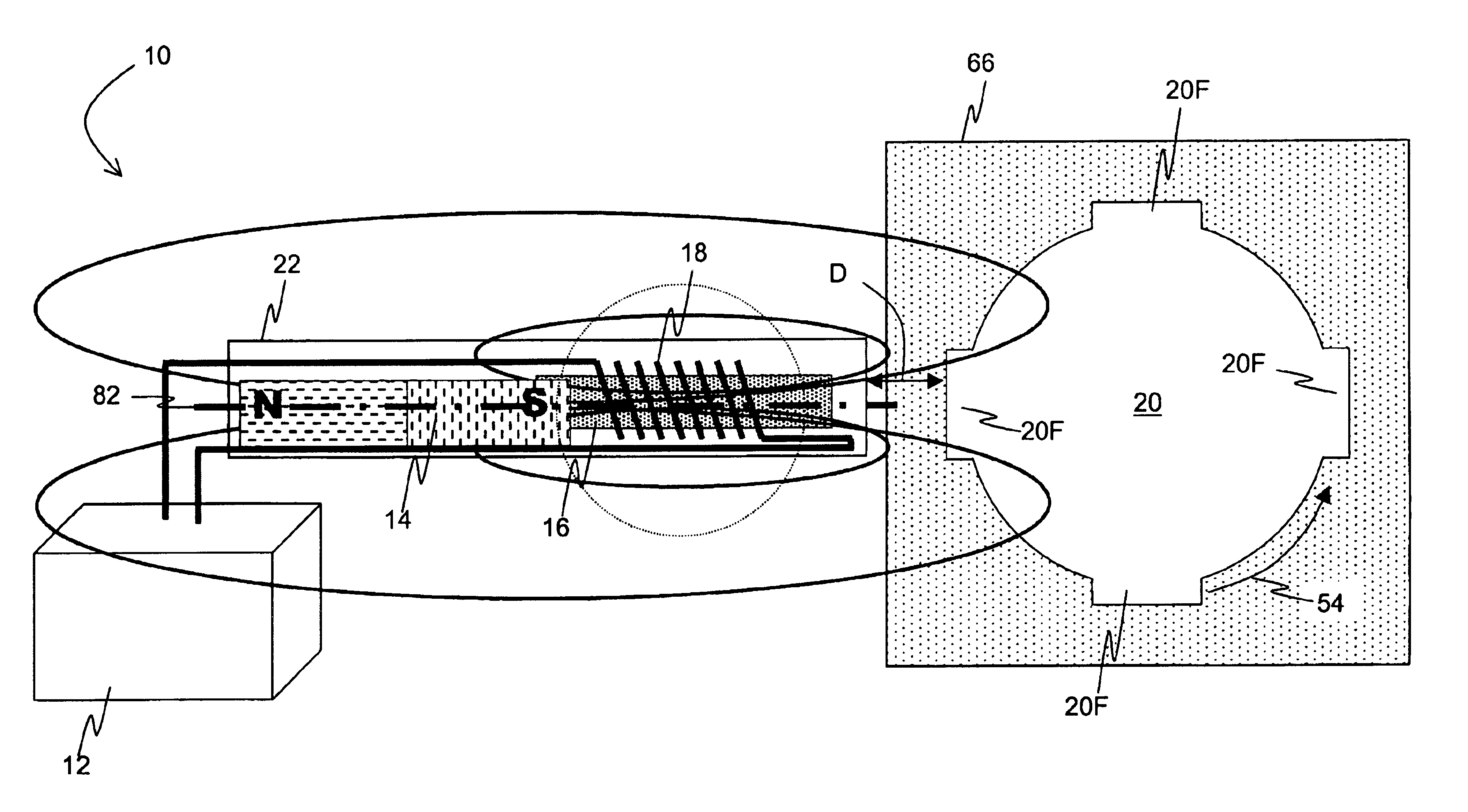
[0030]Referring now to FIG. 4A and FIG. 8, in a currently preferred embodiment of the present disclosure, hybrid inductive sensor 10 includes excitation means 12, permanent magnet 14, pole piece 16, and sensor coil 18 for sensing target surface velocity and or proximity to target 20. Permanent magnet 14 may be any suitable material providing sufficient low frequency field strength such as a permanent magnet or a electromagnet. Pole piece 16 may be of any suitable permeable and / or conductive material exhibiting a low retained magnetization such as iron, steel, or nickel. Pole piece 16 may also be somewhat diamagnetic as a function of frequency.

[0031]There are numerous materials that appear diamagnetic when exposed to a changing magnetic field. Many conductive materials exhibit an apparent diamagnetism. The mechanism by which a changing magnetic field induces a voltage in a pickup coil is replicated to a lesser or greater degree in any solid conductive material such as a block of copp...


PUM


Abstract

A hybrid speed and or proximity sensor may include a variable reluctance sensor with an added excitation circuit. Similarly, a hybrid speed and or proximity sensor may include a variable inductance proximity sensor having a magnet and a magnetically permeable pole piece added in the sensor. It is emphasized that this abstract is provided to comply with the rules requiring an abstract, which will allow a searcher or other reader to quickly ascertain the subject matter of the technical disclosure. It is submitted with the understanding that it will not be used to interpret or limit the scope or meaning of the claims.

Description

BACKGROUND OF THE INVENTION[0001]1. Field of Invention[0002]The present invention relates generally to the field of inductive sensors and more particularly to hybrid inductive speed and proximity sensors that measure speeds approaching zero.[0003]2. Background Information[0004]Rotary and linear inductive sensors, such as the variable reluctance speed sensor (VRSS) as shown in FIG. 1, or variable inductance proximity sensors as shown in FIG. 2 or induction sensors using permanent magnets on the target as shown in FIG. 3, have many years of reliable service. However, conventional, manned flight approved sensors can not accurately measure speeds approaching zero and have difficulty measuring the speed of targets without surface irregularities and also require close proximity between the sensor and the target. Variable reluctance speed sensors and induction sensors, either rotary or linear, require movement of a scrutinized target to generate a signal used to monitor speed. Accordingly,...

Claims


Application Information

Patent Timeline
Patent Type & Authority Patents(United States)
IPC IPC(8): G01B7/00G01D5/20G01P3/487G01P3/488
CPCG01B7/003G01D5/2013G01D5/202G01P3/487G01P3/488
Inventor SCHWARTZBART, AARON
Owner THE BOEING CO
Why Eureka
Try Eureka