Controlling resonant photoelastic modulators

a resonant photoelastic modulator and resonant technology, applied in the field of precise control of resonant photoelastic modulators, can solve the problems of uncontrolled oscillation frequency control by users, uncontrolled oscillation frequency control, and inability to precisely drive pems at resonance, so as to improve the performance of pems

Inactive Publication Date: 2005-11-29
HINDS INSTR
View PDF2 Cites 8 Cited by
  • Summary
  • Abstract
  • Description
  • Claims
  • Application Information

AI Technical Summary

Benefits of technology

[0014]The present invention is directed to a practical system and method for exploiting the dependence of a PEM's resonance f...

Problems solved by technology

However, driving PEMs at their resonant frequency prevents the user from controlling the oscillation frequency.
This is because even a relatively small spread in the resonant frequencies of the individual PEMs, which is fully consistent with manufacturing specifications, results in most of the PEMs not being driven exactly at resonance.
Furthermore, uneven heating of the individual PEMs when driven at high amplitudes may result ...

Method used


Image

  • Controlling resonant photoelastic modulators
  • Controlling resonant photoelastic modulators
  • Controlling resonant photoelastic modulators

Examples


Embodiment Construction

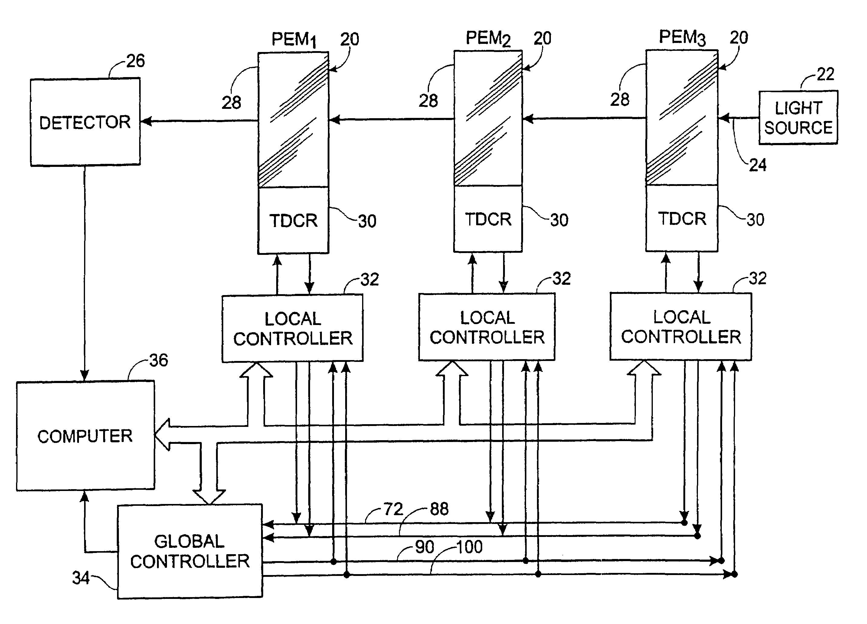
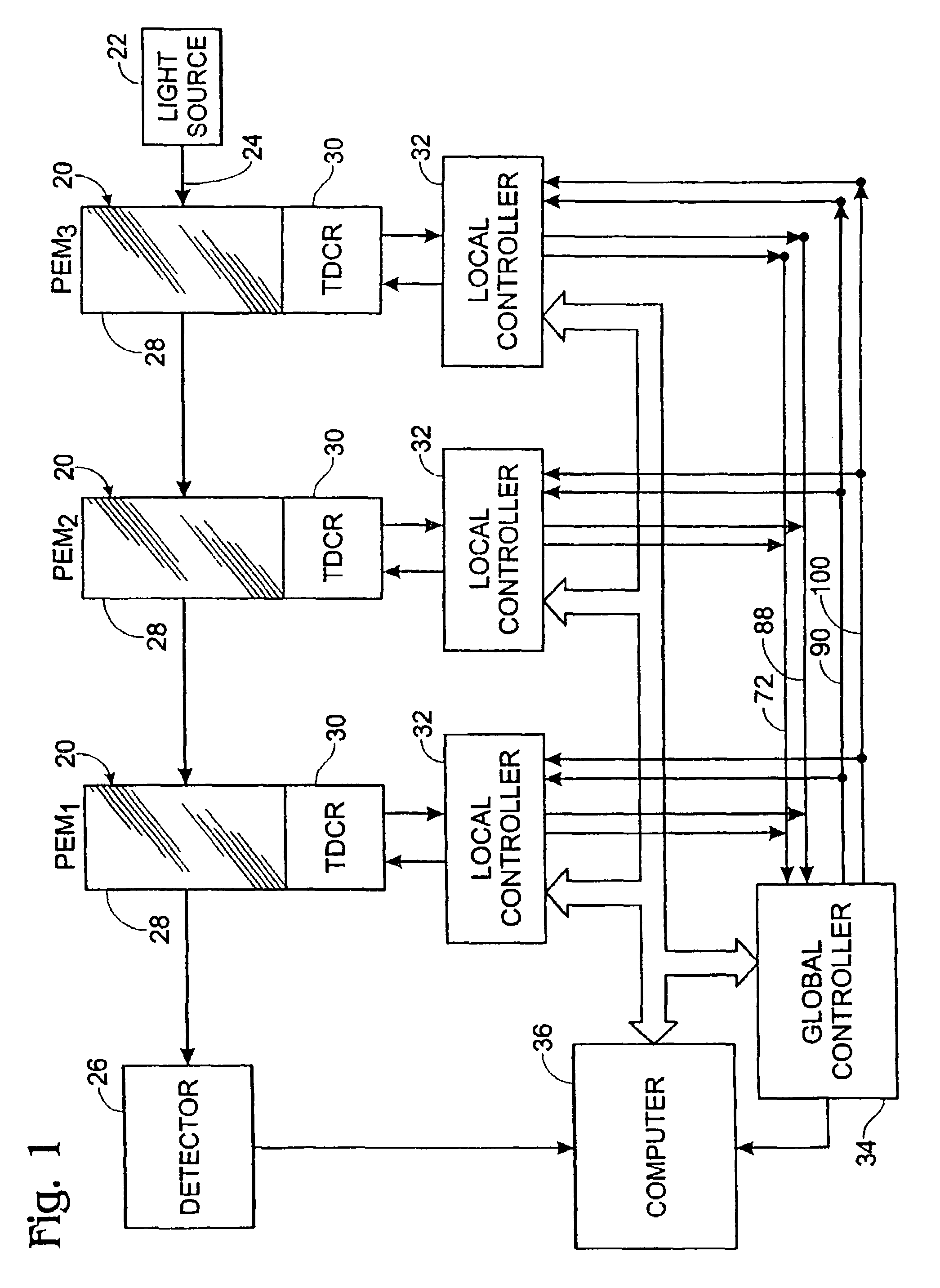
[0025]The diagram of FIG. 1 depicts an exemplary system for controlling multiple photoelastic modulators (PEMs) in accordance with one aspect of the present invention. In this embodiment, a series of three PEMs 20 are depicted. The PEMs are aligned so that light from a source 22 travels in a beam 24 through each of the PEMs 20 to reach a detector 26. The optical aspects of the setup shown in FIG. 1 have been greatly simplified (polarizers, etc. being omitted) for the purposes of this description. Such a setup may be used, for example, in the Fourier Transform spectral analysis mentioned above.

[0026]The polarization of the light 24 is modulated by the PEMs to impart a retardation amplitude in the beam that reaches the detector. In this regard, the optical element 28 of each PEM is vibrated by an attached piezoelectric transducer 30, thereby to introduce into the optical element (such as fused silica) the oscillating birefringence discussed above (as well as the attendant contribution...


PUM


Abstract

A system and method for exploiting the dependance of a photoelastic modulator's (PEM's) resonance frequency on temperature (attributable to driving amplitude and to ambient temperature) to generally improve the performance of PEMs. In one embodiment there is provided a method and system for efficiently driving a series of multiple PEMs. To this end, each of the PEMs in a stack are separately tuned, as by controlling the power dissipated in each PEM, so that the resonance frequencies of all of the PEMs converge to a common frequency. Thus, all of the PEMs are simultaneously at resonance to ensure maximum efficiency and to maintain a selected total retardation amplitude. In another embodiment of the present invention, a single-element PEM is controlled in a manner to account for the subtle changes in the PEM's resonance frequency. To this end a control method and system is provided to keep constant both the retardation amplitude of the PEM and the actual operating frequency of the PEM, which frequency need not necessarily be the resonant frequency.

Description

[0001]This application is a national stage of PCT / US99 / 05586, filed Mar. 16, 1999, which claims the benefit under 35 USC 119(c) of US Provisional Application 60 / 078,069, filed Mar. 16, 1998.TECHNICAL FIELD[0002]This application relates to a system and method for precise control of resonant photoelastic modulators.BACKGROUND[0003]A resonant photoelastic modulator (PEM) is an instrument that is used for modulating the polarization of a beam of light. A PEM employs the photoelastic effect as a principle of operation. The term “photoelastic effect” means that an optical element that is mechanically strained (deformed) exhibits birefringence that is proportional to the amount of strain induced into the element. Birefringence means that the refractive index of the element is different for different components of polarized light.[0004]A PEM includes an optical element, such as fused silica, that has attached to it a piezoelectric transducer for vibrating the optical element at a fixed freq...

Claims


Application Information

Patent Timeline
IPC IPC(8): G02B9/02G02F1/01G02F1/33
CPCG02F1/0123G02F1/0131G02F2201/16
Inventor BUICAN, TUDOR N.
Owner HINDS INSTR
Why Eureka
Try Eureka